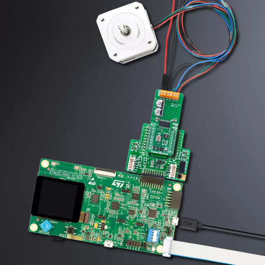
Deliver smooth and accurate stepper motor motion with DRV8452 and STM32L496AG
High-power, ultra-precise control for bipolar stepper motors
Published Jul 22, 2025
Click board™
Stepper 25 Click
Dev. board
Discovery kit with STM32L496AG MCU
Compiler
NECTO Studio
MCU
STM32L496AG
Achieve ultra-precise bipolar stepper motor control with 1/256 microstepping and a powerful 5A full-scale output
A
A
Hardware Overview
How does it work?
Stepper 25 Click is based on the DRV8452 motor driver IC from Texas Instruments for precise control of bipolar stepper motors. The DRV8452 includes two N-channel power MOSFET H-bridges, current sense resistors, an advanced current regulation system, and a microstepping indexer, all within a single package. This robust integration enables the board to handle a wide supply voltage range from 4.5V to 55V, while delivering an impressive output current of up to 5A full-scale, or 3.5A RMS, ensuring stable performance in high-power scenarios. Thanks to the capabilities of the DRV8452, Stepper 25 Click is ideally suited for a wide range of applications including textile and sewing machines, factory automation systems, robotic platforms, diagnostic equipment, multifunction printers, as well as PLC, DCS, and PAC-based systems. This makes it a versatile and reliable choice for engineers and developers working on complex motion control tasks that demand both power and precision. One of the standout features of the DRV8452 is the auto-torque function, which dynamically adjusts the output current based on the motor load. This not only enhances the overall efficiency of the system but also significantly reduces power losses during operation. Fine-tuning of the motor current is made simple through the onboard VREF trimmer, allowing for precise adjustments to match specific load requirements. Additionally, the board includes an ENABLE switch that allows users to control the activation of the output channels - when set to
position 0, all outputs are disabled, and when set to position 1, the outputs are enabled and ready for operation. Stepper 25 Click uses a standard 4-wire SPI interface for communication with the host MCU, allowing precise configuration of the DRV8452 and optimization of the auto-torque algorithm for various motor applications. It features stall detection to notify the system when the motor is blocked or reaches its travel limit, ensuring safe operation. To reduce energy usage, the standstill power saving mode minimizes power loss when the motor is holding position. The DRV8452 also includes an integrated current-sense architecture that eliminates the need for external sense resistors by using a current mirror and internal MOSFETs. A combination of STP and DIR pins allows a host MCU to manage the direction and step rate of the stepper motor. The integrated microstepping indexer of the DRV8452 enables precise motion control without requiring the host to manage winding currents. The indexer supports a wide range of resolutions, including full step, half step, and microsteps down to 1/256, ensuring exceptionally smooth and accurate motion. Higher microstepping levels significantly reduce audible noise and enhance movement fluidity. Additionally, the automatic microstepping mode interpolates low-frequency input signals into high-resolution steps, improving current regulation and further minimizing noise during operation. To regulate the winding current effectively, the DRV8452 use various decay modes such as slow, mixed, and fast decay. The
DRV8452 also features advanced smart tune decay modes that automatically adapt to ensure optimal current regulation, regardless of changes in supply voltage, motor speed, or aging. Smart tune Ripple Control employs a variable off-time ripple current scheme to reduce current distortion in the motor windings, while Smart tune Dynamic Decay uses a fixed off-time with dynamic fast decay percentages for improved performance. In addition to these, the DRV8452 includes a silent step decay mode designed to enable extremely quiet operation during standstill and low-speed motion. Stepper 25 Click features two additional control pins: FLT and SLP. The FLT pin serves as a fault indicator, signaling any fault conditions such as overcurrent or thermal shutdown. The SLP pin controls the device’s power mode - setting it to logic HIGH enables normal operation, while logic LOW puts the device into a low-power sleep mode to conserve energy. Both pins are paired with red LED indicators labeled FAULT and SLEEP, providing clear visual feedback on the device’s fault status and power state for easier monitoring and debugging. This Click board™ can operate with either 3.3V or 5V logic voltage levels selected via the VCC SEL jumper. This way, both 3.3V and 5V capable MCUs can use the communication lines properly. Also, this Click board™ comes equipped with a library containing easy-to-use functions and an example code that can be used as a reference for further development.

Features overview
Development board
The 32L496GDISCOVERY Discovery kit serves as a comprehensive demonstration and development platform for the STM32L496AG microcontroller, featuring an Arm® Cortex®-M4 core. Designed for applications that demand a balance of high performance, advanced graphics, and ultra-low power consumption, this kit enables seamless prototyping for a wide range of embedded solutions. With its innovative energy-efficient
architecture, the STM32L496AG integrates extended RAM and the Chrom-ART Accelerator, enhancing graphics performance while maintaining low power consumption. This makes the kit particularly well-suited for applications involving audio processing, graphical user interfaces, and real-time data acquisition, where energy efficiency is a key requirement. For ease of development, the board includes an onboard ST-LINK/V2-1
debugger/programmer, providing a seamless out-of-the-box experience for loading, debugging, and testing applications without requiring additional hardware. The combination of low power features, enhanced memory capabilities, and built-in debugging tools makes the 32L496GDISCOVERY kit an ideal choice for prototyping advanced embedded systems with state-of-the-art energy efficiency.

Microcontroller Overview
MCU Card / MCU

Architecture
ARM Cortex-M4
MCU Memory (KB)
1024
Silicon Vendor
STMicroelectronics
Pin count
169
RAM (Bytes)
327680
You complete me!
Accessories
The 17HD40005-22B stepper motor is a two-phase hybrid motor for high torque, high speed, and low noise performance. It features a 1m wire with optional ports on the connection end and heat shrink tubing to prevent tangling. The motor's D-shaped axle is 22mm in length. This motor operates with a chopping wave constant current drive and has a two-phase 4-wire exciting mode, allowing for both forward and reverse rotation. The power order follows AB-BC-CD-DA, viewed as clockwise from the shaft end. It has a rated current of 1.3A DC, a rated voltage of 2.4V, and a stepping angle of 1.8°, with an insulation grade of B. This stepper motor is ideal for applications requiring precise movement control and reliability.

Used MCU Pins
mikroBUS™ mapper
Take a closer look
Click board™ Schematic

Step by step
Project assembly

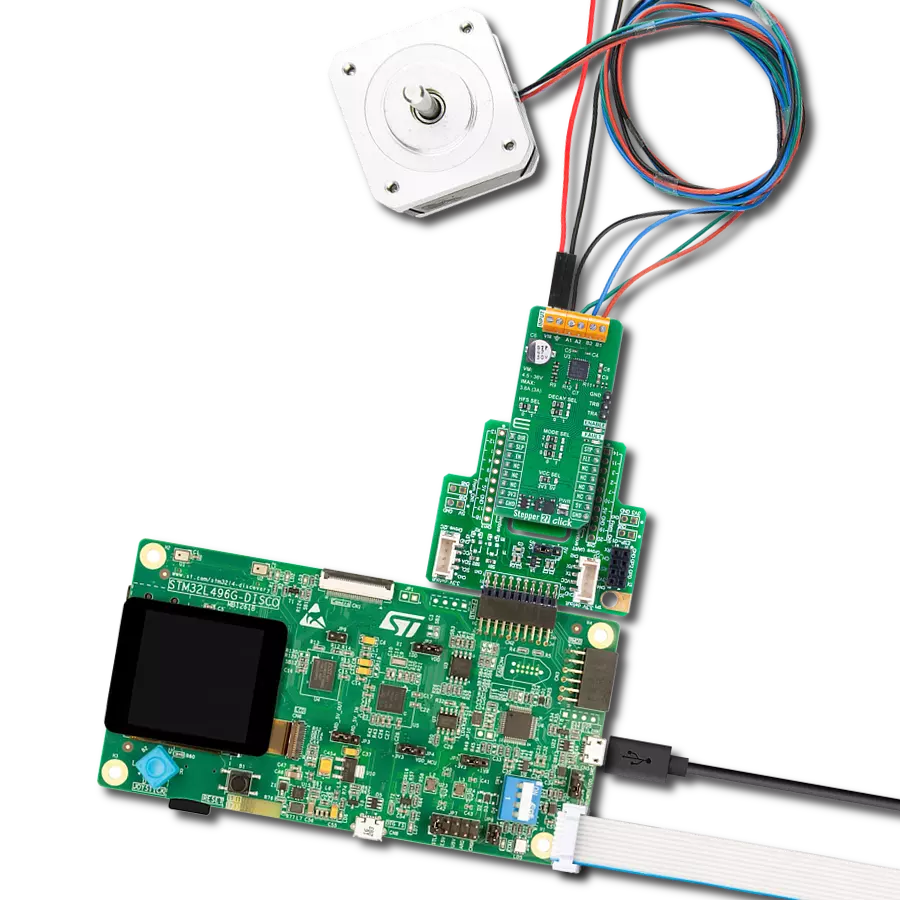
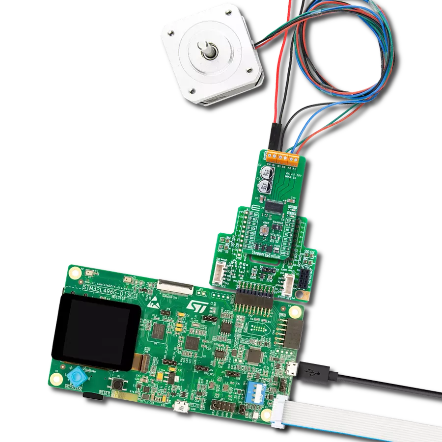
Start by selecting your development board and Click board™. Begin with the Discovery kit with STM32L496AG MCU as your development board.


Track your results in real time
Application Output
1. Application Output - In Debug mode, the 'Application Output' window enables real-time data monitoring, offering direct insight into execution results. Ensure proper data display by configuring the environment correctly using the provided tutorial.

2. UART Terminal - Use the UART Terminal to monitor data transmission via a USB to UART converter, allowing direct communication between the Click board™ and your development system. Configure the baud rate and other serial settings according to your project's requirements to ensure proper functionality. For step-by-step setup instructions, refer to the provided tutorial.

3. Plot Output - The Plot feature offers a powerful way to visualize real-time sensor data, enabling trend analysis, debugging, and comparison of multiple data points. To set it up correctly, follow the provided tutorial, which includes a step-by-step example of using the Plot feature to display Click board™ readings. To use the Plot feature in your code, use the function: plot(*insert_graph_name*, variable_name);. This is a general format, and it is up to the user to replace 'insert_graph_name' with the actual graph name and 'variable_name' with the parameter to be displayed.

Software Support
Library Description
Stepper 25 Click demo application is developed using the NECTO Studio, ensuring compatibility with mikroSDK's open-source libraries and tools. Designed for plug-and-play implementation and testing, the demo is fully compatible with all development, starter, and mikromedia boards featuring a mikroBUS™ socket.
Example Description
This example demonstrates the operation of the Stepper 25 Click board, which is used to control a bipolar stepper motor. The application initializes the board and executes different step modes, directions, and speeds to showcase precise motor control.
Key functions:
stepper25_cfg_setup- This function initializes Click configuration structure to initial values.stepper25_init- This function initializes all necessary pins and peripherals used for this Click board.stepper25_default_cfg- Click Default Configuration function.stepper25_set_direction- This function sets the motor direction by setting the DIR pin logic state.stepper25_set_step_mode- This function sets the step mode (microstepping level) of the Stepper 25 device.stepper25_drive_motor- This function drives the motor for the specific number of steps at the selected speed.
Application Init
Initializes the logger and Stepper 25 Click board. Configures the motor driver with default settings, preparing it for stepper motor control.
Application Task
Moves the stepper motor in different step modes and directions at varying speeds. The motor completes a predefined number of steps in each mode, switching between clockwise (CW) and counterclockwise (CCW) directions with different step resolutions.
Open Source
Code example
The complete application code and a ready-to-use project are available through the NECTO Studio Package Manager for direct installation in the NECTO Studio. The application code can also be found on the MIKROE GitHub account.
/*!
 * @file main.c
 * @brief Stepper 25 Click example
 *
 * # Description
 * This example demonstrates the operation of the Stepper 25 Click board,
 * which is used to control a bipolar stepper motor. The application initializes
 * the board and executes different step modes, directions, and speeds to
 * showcase precise motor control.
 *
 * The demo application is composed of two sections:
 *
 * ## Application Init
 * Initializes the logger and Stepper 25 Click board. Configures the motor driver
 * with default settings, preparing it for stepper motor control.
 *
 * ## Application Task
 * Moves the stepper motor in different step modes and directions at varying speeds.
 * The motor completes a predefined number of steps in each mode, switching between
 * clockwise (CW) and counterclockwise (CCW) directions with different step resolutions.
 *
 * @note
 * Ensure proper power supply and motor connections before running the example.
 *
 * @author Stefan Filipovic
 *
 */

#include "board.h"
#include "log.h"
#include "stepper25.h"

static stepper25_t stepper25;
static log_t logger;

void application_init ( void )
{
    log_cfg_t log_cfg;  /**< Logger config object. */
    stepper25_cfg_t stepper25_cfg;  /**< Click config object. */

    /**
     * Logger initialization.
     * Default baud rate: 115200
     * Default log level: LOG_LEVEL_DEBUG
     * @note If USB_UART_RX and USB_UART_TX
     * are defined as HAL_PIN_NC, you will
     * need to define them manually for log to work.
     * See @b LOG_MAP_USB_UART macro definition for detailed explanation.
     */
    LOG_MAP_USB_UART( log_cfg );
    log_init( &logger, &log_cfg );
    log_info( &logger, " Application Init " );

    // Click initialization.
    stepper25_cfg_setup( &stepper25_cfg );
    STEPPER25_MAP_MIKROBUS( stepper25_cfg, MIKROBUS_1 );
    if ( SPI_MASTER_ERROR == stepper25_init( &stepper25, &stepper25_cfg ) )
    {
        log_error( &logger, " Communication init." );
        for ( ; ; );
    }

    if ( STEPPER25_ERROR == stepper25_default_cfg ( &stepper25 ) )
    {
        log_error( &logger, " Default configuration." );
        for ( ; ; );
    }

    log_info( &logger, " Application Task " );
}

void application_task ( void )
{
    log_printf ( &logger, " Step mode: 1/16\r\n" );
    log_printf ( &logger, " Direction: CW\r\n" );
    log_printf ( &logger, " Steps: 1600\r\n" );
    log_printf ( &logger, " Speed: Medium\r\n\n" );
    stepper25_set_direction ( &stepper25, STEPPER25_DIR_CW );
    stepper25_set_step_mode ( &stepper25, STEPPER25_STEP_MODE_1_OVER_16 );
    stepper25_drive_motor ( &stepper25, 1600, STEPPER25_SPEED_MEDIUM );
    Delay_ms ( 1000 );

    log_printf ( &logger, " Step mode: 1/8\r\n" );
    log_printf ( &logger, " Direction: CCW\r\n" );
    log_printf ( &logger, " Steps: 1600\r\n" );
    log_printf ( &logger, " Speed: Fast\r\n\n" );
    stepper25_set_direction ( &stepper25, STEPPER25_DIR_CCW );
    stepper25_set_step_mode ( &stepper25, STEPPER25_STEP_MODE_1_OVER_8 );
    stepper25_drive_motor ( &stepper25, 1600, STEPPER25_SPEED_FAST );
    Delay_ms ( 1000 );

    log_printf ( &logger, " Step mode: 1/4\r\n" );
    log_printf ( &logger, " Direction: CW\r\n" );
    log_printf ( &logger, " Steps: 400\r\n" );
    log_printf ( &logger, " Speed: Slow\r\n\n" );
    stepper25_set_direction ( &stepper25, STEPPER25_DIR_CW );
    stepper25_set_step_mode ( &stepper25, STEPPER25_STEP_MODE_QUARTER );
    stepper25_drive_motor ( &stepper25, 400, STEPPER25_SPEED_SLOW );
    Delay_ms ( 1000 );
}

int main ( void )
{
    /* Do not remove this line or clock might not be set correctly. */
    #ifdef PREINIT_SUPPORTED
    preinit();
    #endif

    application_init( );

    for ( ; ; )
    {
        application_task( );
    }

    return 0;
}

// ------------------------------------------------------------------------ END
Additional Support
Resources
Category:Stepper