Achieve LTE-M and NB-IoT connectivity with global coverage using GM02S and PIC32MZ2048EFM100
Dual-mode LTE-M/NB-IoT solution for worldwide deployments
Published Mar 05, 2025
Click board™
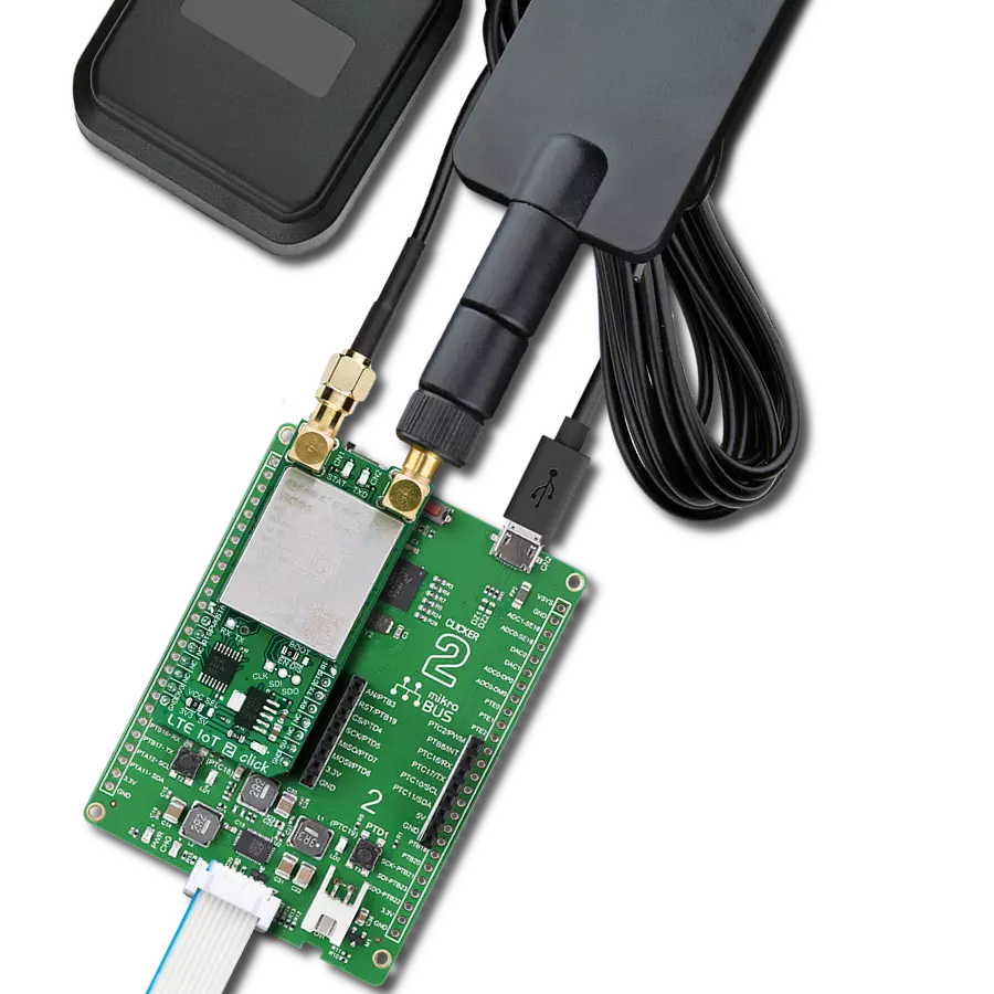
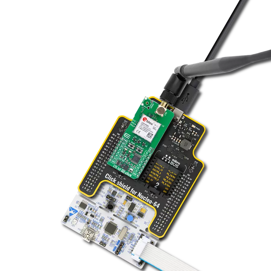
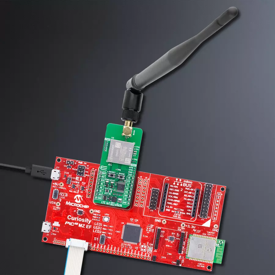
LTE IoT 10 Click
Dev. board
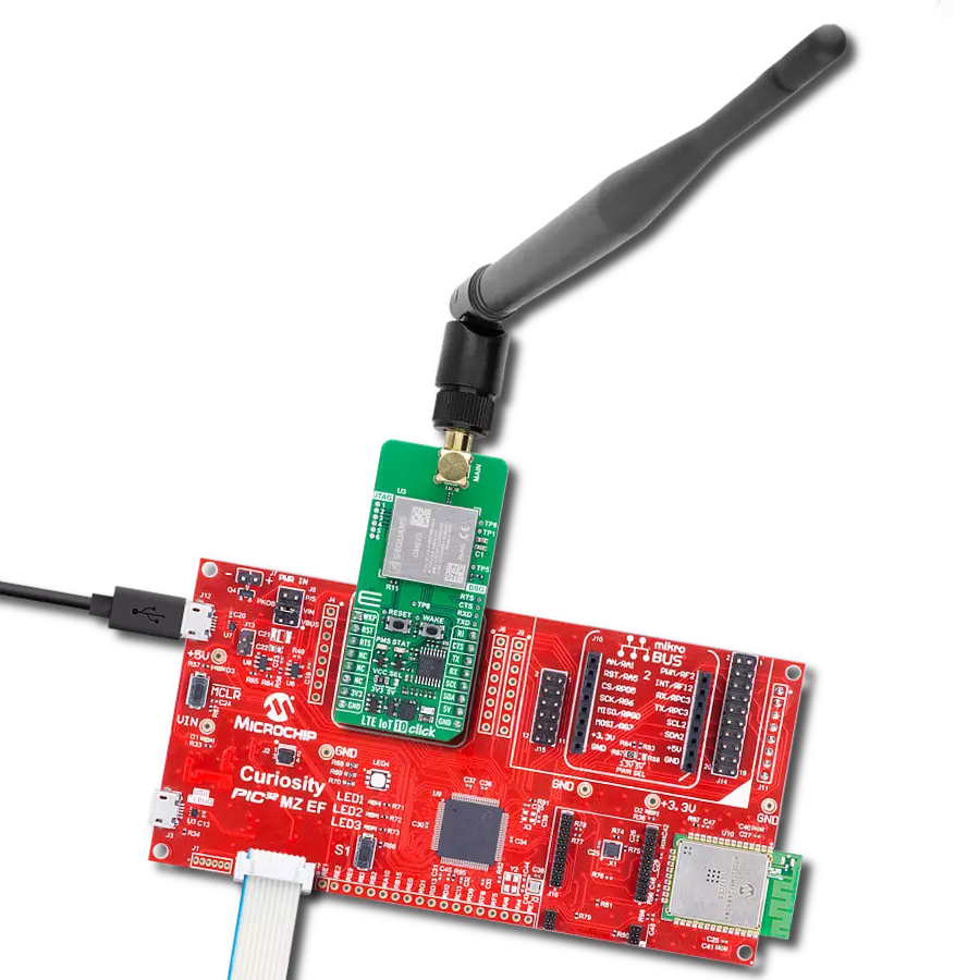
Curiosity PIC32 MZ EF
Compiler
NECTO Studio
MCU
PIC32MZ2048EFM100
LTE-M and NB-IoT connectivity with global band support perfect for smart meters, asset tracking, and industrial IoT applications
A
A
Hardware Overview
How does it work?
LTE IoT 10 Click is based on the Monarch 2 GM02S module from Sequans, designed to provide reliable LTE-M and NB-IoT connectivity. The GM02S is a highly optimized dual-mode LTE-M and NB-IoT solution featuring global band support from 617MHz to 2.2GHz (bands 1,2,3,4,5,8,12,13,14,17,18,19,20,25,26,28,66,85), making it compatible with both public and private LTE networks worldwide. The board can be used for attaching to LTE live network or test equipment (CMW500 or similar). Engineered with Sequans' second-generation Monarch 2 chip platform (Sequans SQN3430 Chipset), this module ensures superior performance, significantly reduced power consumption (industry lowest deep sleep mode at 1μA and best-in-class eDRX and PSM), and robust security, making it an ideal solution for industrial and commercial IoT solutions requiring low power and high reliability, including smart meters, industrial sensors, asset tracking systems, smart home and city applications, wearable devices, and healthcare monitoring solutions. The GM02S module leverages over 15 years of Sequans' expertise in 4G+ connectivity and comes with a mature, carrier-approved LTE protocol stack, ensuring seamless network integration. Its Single-SKU™ RF front end allows operation across all global LTE bands, eliminating the need for regional variations and simplifying deployment. With a transmission power of +23dBm across all bands, the GM02S delivers strong and stable connectivity, even in challenging environments. Additionally, the
module complies with 3GPP LTE Release 14, with the potential for future upgrades up to Release 17, ensuring long-term compatibility with evolving network standards. One of the key advantages of the GM02S module is its ability to switch between LTE-M and NB-IoT modes (Cat M1, NB1, NB2) with a single firmware image, providing unmatched flexibility in various IoT implementations. It also incorporates an embedded IP stack, supporting TCP with TLS 1.3, UDP with DTLS 1.2, CoAP/MQTT, HTTP/FTP, and more, making it well-suited for secure data communication. Communication between the GM02S and the host MCU is made through a UART interface, using standard UART RX and TX pins and hardware flow control pins (CTS/RTS/RI - Clear to Send/Ready to Send/Ring Indicator) for data transfer with a default communication speed of 115200bps. The board also features a FW upgrade switch on the back of the board labeled UBOOT to manage firmware upgrades. This switch has positions 0 for normal operation and 1 for firmware upgrade, ensuring a straightforward upgrade process. A dedicated UART interface is available through test points labeled as DBG for debugging and module upgrades. In addition, the board also features JTAG interface pins, an industry-standard solution for verifying designs and testing printed circuit boards. The LTE IoT 10 Click includes several additional functionalities that enhance its usability and control. The WAKE button allows users to wake the module from Sleep mode, while the RESET button
provides a quick way to reset the module. These functions can also be controlled digitally via the mikroBUS™ pins WKP and RST, offering greater flexibility. Moreover, these controls have dedicated test points for easier debugging and testing. The board also features some visual indicators to provide real-time status updates. The first red PMS LED signals the power-saving status, giving insight into the module's low-power operation mode. The second yellow STAT LED indicates the module's power status, ensuring real-time monitoring of its operational state. The board features one SMA connector for the main LTE antenna that MIKROE offers, like the LTE Flat Rotation Antenna or LTE Rubber Antenna, for flexible and efficient connectivity options. The board has a micro SIM card holder that supports 1.8V uSIM cards, ensuring compatibility with a wide range of cellular networks and allowing users to select the most appropriate service provider for their particular use case. This Click board™ can operate with both 3.3V and 5V logic voltage levels selected via the VCC SEL jumper. Since the GM02S module communicates at 1.8V, logic-level translators, the TXB0106 and PCA9306, are also used for proper operation and an accurate signal-level translation. This way, both 3.3V and 5V capable MCUs can use the communication lines properly. Also, this Click board™ comes equipped with a library containing easy-to-use functions and an example code that can be used as a reference for further development.

Features overview
Development board
Curiosity PIC32 MZ EF development board is a fully integrated 32-bit development platform featuring the high-performance PIC32MZ EF Series (PIC32MZ2048EFM) that has a 2MB Flash, 512KB RAM, integrated FPU, Crypto accelerator, and excellent connectivity options. It includes an integrated programmer and debugger, requiring no additional hardware. Users can expand
functionality through MIKROE mikroBUS™ Click™ adapter boards, add Ethernet connectivity with the Microchip PHY daughter board, add WiFi connectivity capability using the Microchip expansions boards, and add audio input and output capability with Microchip audio daughter boards. These boards are fully integrated into PIC32’s powerful software framework, MPLAB Harmony,
which provides a flexible and modular interface to application development a rich set of inter-operable software stacks (TCP-IP, USB), and easy-to-use features. The Curiosity PIC32 MZ EF development board offers expansion capabilities making it an excellent choice for a rapid prototyping board in Connectivity, IOT, and general-purpose applications.

Microcontroller Overview
MCU Card / MCU

Architecture
PIC32
MCU Memory (KB)
2048
Silicon Vendor
Microchip
Pin count
100
RAM (Bytes)
524288
You complete me!
Accessories
LTE Flat Rotation Antenna is a versatile choice for boosting the performance of 3G/4G LTE devices. With a wide frequency range of 700-2700MHz, it ensures optimal connectivity on major cellular bands worldwide. This flat antenna features an SMA male connector, making it easy to attach directly to your device or SMA module connector. One of its standout features is its adjustable angle, which can be set in 45⁰ increments (0⁰/45⁰/90⁰), allowing you to fine-tune the antenna's orientation for maximum signal reception. With an impedance of 50Ω and a VSW Ratio of <2.0:1, this antenna ensures a reliable and efficient connection. Its 5dB gain, vertical polarization, and omnidirectional radiation pattern enhance signal strength, making it suitable for various applications. Measuring 196mm in length and 38mm in width, this antenna offers a compact yet effective solution for improving your connectivity. With a maximum input power of 50W, it can handle the demands of various devices.

This multiband LTE Rubber Antenna with adjustable angle is an excellent choice for all 3G/4G LTE-based click boards from our offer, as well as other devices that require excellent throughput on all major cellular bands worldwide. The antenna has an SMA male connector, which allows it to be mounted directly on the Click board™ or the female SMA module connector. The antenna position can be adjusted in 45⁰ increments (0⁰/45⁰/90⁰).

Used MCU Pins
mikroBUS™ mapper
Take a closer look
Click board™ Schematic

Step by step
Project assembly

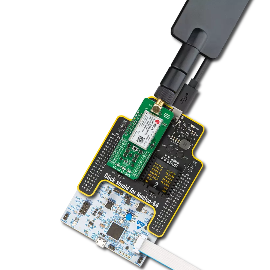
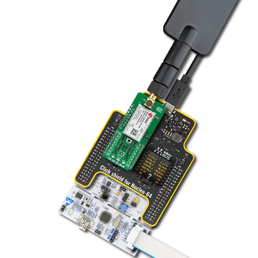
Start by selecting your development board and Click board™. Begin with the Curiosity PIC32 MZ EF as your development board.


Software Support
Library Description
LTE IoT 10 Click demo application is developed using the NECTO Studio, ensuring compatibility with mikroSDK's open-source libraries and tools. Designed for plug-and-play implementation and testing, the demo is fully compatible with all development, starter, and mikromedia boards featuring a mikroBUS™ socket.
Example Description
Application example shows device capability of connecting to the network and sending SMS or TCP/UDP messages using standard "AT" commands.
Key functions:
lteiot10_cfg_setup- This function initializes Click configuration structure to initial values.lteiot10_init- This function initializes all necessary pins and peripherals used for this Click board.lteiot10_set_sim_apn- This function sets APN for sim card.lteiot10_send_sms_text- This function sends text message to a phone number.lteiot10_cmd_set- This function sets a value to a specified command of the Click module.
Application Init
Initializes the driver and logger.
Application Task
Application task is split in few stages:
LTEIOT10_POWER_UP:Powers up the device, performs a device factory reset and reads system information.LTEIOT10_CONFIG_CONNECTION:Sets configuration to device to be able to connect to the network.LTEIOT10_CHECK_CONNECTION:Waits for the network registration indicated via CEREG command and then checks the signal quality report.LTEIOT10_CONFIG_EXAMPLE:Configures device for the selected example.LTEIOT10_EXAMPLE:Depending on the selected demo example, it sends an SMS message (in PDU or TXT mode) or TCP/UDP message. By default, the TCP/UDP example is selected.
Open Source
Code example
The complete application code and a ready-to-use project are available through the NECTO Studio Package Manager for direct installation in the NECTO Studio. The application code can also be found on the MIKROE GitHub account.
/*!
* @file main.c
* @brief LTE IoT 10 Click Example.
*
* # Description
* Application example shows device capability of connecting to the network and
* sending SMS or TCP/UDP messages using standard "AT" commands.
*
* The demo application is composed of two sections :
*
* ## Application Init
* Initializes the driver and logger.
*
* ## Application Task
* Application task is split in few stages:
* - LTEIOT10_POWER_UP:
* Powers up the device, performs a device factory reset and reads system information.
*
* - LTEIOT10_CONFIG_CONNECTION:
* Sets configuration to device to be able to connect to the network.
*
* - LTEIOT10_CHECK_CONNECTION:
* Waits for the network registration indicated via CEREG command and then checks the signal quality report.
*
* - LTEIOT10_CONFIG_EXAMPLE:
* Configures device for the selected example.
*
* - LTEIOT10_EXAMPLE:
* Depending on the selected demo example, it sends an SMS message (in PDU or TXT mode) or TCP/UDP message.
*
* By default, the TCP/UDP example is selected.
*
* ## Additional Function
* - static void lteiot10_clear_app_buf ( void )
* - static void lteiot10_log_app_buf ( void )
* - static err_t lteiot10_process ( lteiot10_t *ctx )
* - static err_t lteiot10_read_response ( lteiot10_t *ctx, uint8_t *rsp )
* - static err_t lteiot10_power_up ( lteiot10_t *ctx )
* - static err_t lteiot10_config_connection ( lteiot10_t *ctx )
* - static err_t lteiot10_check_connection ( lteiot10_t *ctx )
* - static err_t lteiot10_config_example ( lteiot10_t *ctx )
* - static err_t lteiot10_example ( lteiot10_t *ctx )
*
* @note
* In order for the examples to work, user needs to set the APN and SMSC (SMS PDU mode only)
* of entered SIM card as well as the phone number (SMS mode only) to which he wants to send an SMS.
* Enter valid values for the following macros: SIM_APN, SIM_SMSC and PHONE_NUMBER.
* Example:
SIM_APN "internet"
SIM_SMSC "+381610401"
PHONE_NUMBER "+381659999999"
*
* @author Stefan Filipovic
*
*/
#include "board.h"
#include "log.h"
#include "lteiot10.h"
#include "conversions.h"
// Example selection macros
#define EXAMPLE_TCP_UDP 0 // Example of sending messages to a TCP/UDP echo server
#define EXAMPLE_SMS 1 // Example of sending SMS to a phone number
#define DEMO_EXAMPLE EXAMPLE_TCP_UDP // Example selection macro
// SIM APN config
#define SIM_APN "internet" // Set valid SIM APN
// SMS example parameters
#define SIM_SMSC "" // Set valid SMS Service Center Address - only in SMS PDU mode
#define PHONE_NUMBER "" // Set Phone number to message
#define SMS_MODE "1" // SMS mode: "0" - PDU, "1" - TXT
// TCP/UDP example parameters
#define REMOTE_IP "54.187.244.144"// TCP/UDP echo server IP address
#define REMOTE_PORT "51111" // TCP/UDP echo server port
// Message content
#define MESSAGE_CONTENT "LTE IoT 10 Click board - demo example."
// Application buffer size
#define APP_BUFFER_SIZE 256
#define PROCESS_BUFFER_SIZE 256
/**
* @brief Example states.
* @details Predefined enum values for application example state.
*/
typedef enum
{
LTEIOT10_POWER_UP = 1,
LTEIOT10_CONFIG_CONNECTION,
LTEIOT10_CHECK_CONNECTION,
LTEIOT10_CONFIG_EXAMPLE,
LTEIOT10_EXAMPLE
} lteiot10_app_state_t;
/**
* @brief Application example variables.
* @details Variables used in application example.
*/
static uint8_t app_buf[ APP_BUFFER_SIZE ] = { 0 };
static int32_t app_buf_len = 0;
static lteiot10_app_state_t app_state = LTEIOT10_POWER_UP;
static lteiot10_t lteiot10;
static log_t logger;
/**
* @brief LTE IoT 10 clearing application buffer.
* @details This function clears memory of application buffer and reset its length.
* @note None.
*/
static void lteiot10_clear_app_buf ( void );
/**
* @brief LTE IoT 10 log application buffer.
* @details This function logs data from application buffer to USB UART.
* @note None.
*/
static void lteiot10_log_app_buf ( void );
/**
* @brief LTE IoT 10 data reading function.
* @details This function reads data from device and concatenates data to application buffer.
* @param[in] ctx : Click context object.
* See #lteiot10_t object definition for detailed explanation.
* @return @li @c 0 - Read some data.
* @li @c -1 - Nothing is read.
* See #err_t definition for detailed explanation.
* @note None.
*/
static err_t lteiot10_process ( lteiot10_t *ctx );
/**
* @brief LTE IoT 10 read response function.
* @details This function waits for a response message, reads and displays it on the USB UART.
* @param[in] ctx : Click context object.
* See #lteiot10_t object definition for detailed explanation.
* @param[in] rsp Expected response.
* @return @li @c 0 - OK response.
* @li @c -2 - Timeout error.
* @li @c -3 - Command error.
* See #err_t definition for detailed explanation.
* @note None.
*/
static err_t lteiot10_read_response ( lteiot10_t *ctx, uint8_t *rsp );
/**
* @brief LTE IoT 10 power up function.
* @details This function powers up the device, performs device factory reset and reads system information.
* @param[in] ctx : Click context object.
* See #lteiot10_t object definition for detailed explanation.
* @return @li @c 0 - OK.
* @li @c != 0 - Read response error.
* See #err_t definition for detailed explanation.
* @note None.
*/
static err_t lteiot10_power_up ( lteiot10_t *ctx );
/**
* @brief LTE IoT 10 config connection function.
* @details This function configures and enables connection to the specified network.
* @param[in] ctx : Click context object.
* See #lteiot10_t object definition for detailed explanation.
* @return @li @c 0 - OK.
* @li @c != 0 - Read response error.
* See #err_t definition for detailed explanation.
* @note None.
*/
static err_t lteiot10_config_connection ( lteiot10_t *ctx );
/**
* @brief LTE IoT 10 check connection function.
* @details This function checks the connection to network.
* @param[in] ctx : Click context object.
* See #lteiot10_t object definition for detailed explanation.
* @return @li @c 0 - OK.
* @li @c != 0 - Read response error.
* See #err_t definition for detailed explanation.
* @note None.
*/
static err_t lteiot10_check_connection ( lteiot10_t *ctx );
/**
* @brief LTE IoT 10 config example function.
* @details This function configures device for the selected example.
* @param[in] ctx : Click context object.
* See #lteiot10_t object definition for detailed explanation.
* @return @li @c 0 - OK.
* @li @c != 0 - Read response error.
* See #err_t definition for detailed explanation.
* @note None.
*/
static err_t lteiot10_config_example ( lteiot10_t *ctx );
/**
* @brief LTE IoT 10 example function.
* @details This function executes SMS or TCP/UDP example depending on the DEMO_EXAMPLE macro.
* @param[in] ctx : Click context object.
* See #lteiot10_t object definition for detailed explanation.
* @return @li @c 0 - OK.
* @li @c != 0 - Read response error.
* See #err_t definition for detailed explanation.
* @note None.
*/
static err_t lteiot10_example ( lteiot10_t *ctx );
void application_init ( void )
{
log_cfg_t log_cfg; /**< Logger config object. */
lteiot10_cfg_t lteiot10_cfg; /**< Click config object. */
/**
* Logger initialization.
* Default baud rate: 115200
* Default log level: LOG_LEVEL_DEBUG
* @note If USB_UART_RX and USB_UART_TX
* are defined as HAL_PIN_NC, you will
* need to define them manually for log to work.
* See @b LOG_MAP_USB_UART macro definition for detailed explanation.
*/
LOG_MAP_USB_UART( log_cfg );
log_init( &logger, &log_cfg );
log_info( &logger, " Application Init " );
// Click initialization.
lteiot10_cfg_setup( <eiot10_cfg );
LTEIOT10_MAP_MIKROBUS( lteiot10_cfg, MIKROBUS_1 );
if ( UART_ERROR == lteiot10_init( <eiot10, <eiot10_cfg ) )
{
log_error( &logger, " Communication init." );
for ( ; ; );
}
log_info( &logger, " Application Task " );
app_state = LTEIOT10_POWER_UP;
log_printf( &logger, ">>> APP STATE - POWER UP <<<\r\n\n" );
}
void application_task ( void )
{
switch ( app_state )
{
case LTEIOT10_POWER_UP:
{
if ( LTEIOT10_OK == lteiot10_power_up( <eiot10 ) )
{
app_state = LTEIOT10_CONFIG_CONNECTION;
log_printf( &logger, ">>> APP STATE - CONFIG CONNECTION <<<\r\n\n" );
}
break;
}
case LTEIOT10_CONFIG_CONNECTION:
{
if ( LTEIOT10_OK == lteiot10_config_connection( <eiot10 ) )
{
app_state = LTEIOT10_CHECK_CONNECTION;
log_printf( &logger, ">>> APP STATE - CHECK CONNECTION <<<\r\n\n" );
}
break;
}
case LTEIOT10_CHECK_CONNECTION:
{
if ( LTEIOT10_OK == lteiot10_check_connection( <eiot10 ) )
{
app_state = LTEIOT10_CONFIG_EXAMPLE;
log_printf( &logger, ">>> APP STATE - CONFIG EXAMPLE <<<\r\n\n" );
}
break;
}
case LTEIOT10_CONFIG_EXAMPLE:
{
if ( LTEIOT10_OK == lteiot10_config_example( <eiot10 ) )
{
app_state = LTEIOT10_EXAMPLE;
log_printf( &logger, ">>> APP STATE - EXAMPLE <<<\r\n\n" );
}
break;
}
case LTEIOT10_EXAMPLE:
{
lteiot10_example( <eiot10 );
break;
}
default:
{
log_error( &logger, " APP STATE." );
break;
}
}
}
int main ( void )
{
/* Do not remove this line or clock might not be set correctly. */
#ifdef PREINIT_SUPPORTED
preinit();
#endif
application_init( );
for ( ; ; )
{
application_task( );
}
return 0;
}
static void lteiot10_clear_app_buf ( void )
{
memset( app_buf, 0, app_buf_len );
app_buf_len = 0;
}
static void lteiot10_log_app_buf ( void )
{
for ( int32_t buf_cnt = 0; buf_cnt < app_buf_len; buf_cnt++ )
{
log_printf( &logger, "%c", app_buf[ buf_cnt ] );
}
}
static err_t lteiot10_process ( lteiot10_t *ctx )
{
uint8_t rx_buf[ PROCESS_BUFFER_SIZE ] = { 0 };
int32_t overflow_bytes = 0;
int32_t rx_cnt = 0;
int32_t rx_size = lteiot10_generic_read( ctx, rx_buf, PROCESS_BUFFER_SIZE );
if ( ( rx_size > 0 ) && ( rx_size <= APP_BUFFER_SIZE ) )
{
if ( ( app_buf_len + rx_size ) > APP_BUFFER_SIZE )
{
overflow_bytes = ( app_buf_len + rx_size ) - APP_BUFFER_SIZE;
app_buf_len = APP_BUFFER_SIZE - rx_size;
memmove ( app_buf, &app_buf[ overflow_bytes ], app_buf_len );
memset ( &app_buf[ app_buf_len ], 0, overflow_bytes );
}
for ( rx_cnt = 0; rx_cnt < rx_size; rx_cnt++ )
{
if ( rx_buf[ rx_cnt ] )
{
app_buf[ app_buf_len++ ] = rx_buf[ rx_cnt ];
}
}
return LTEIOT10_OK;
}
return LTEIOT10_ERROR;
}
static err_t lteiot10_read_response ( lteiot10_t *ctx, uint8_t *rsp )
{
#define READ_RESPONSE_TIMEOUT_MS 120000
uint32_t timeout_cnt = 0;
lteiot10_clear_app_buf( );
lteiot10_process( ctx );
while ( ( 0 == strstr( app_buf, rsp ) ) &&
( 0 == strstr( app_buf, LTEIOT10_RSP_ERROR ) ) )
{
lteiot10_process( ctx );
if ( timeout_cnt++ > READ_RESPONSE_TIMEOUT_MS )
{
lteiot10_log_app_buf( );
lteiot10_clear_app_buf( );
log_error( &logger, " Timeout!" );
return LTEIOT10_ERROR_TIMEOUT;
}
Delay_ms( 1 );
}
Delay_ms ( 200 );
lteiot10_process( ctx );
lteiot10_log_app_buf( );
if ( strstr( app_buf, rsp ) )
{
log_printf( &logger, "--------------------------------\r\n" );
return LTEIOT10_OK;
}
return LTEIOT10_ERROR_CMD;
}
static err_t lteiot10_power_up ( lteiot10_t *ctx )
{
err_t error_flag = LTEIOT10_OK;
log_printf( &logger, ">>> HW reset device.\r\n" );
lteiot10_reset_device( ctx );
error_flag |= lteiot10_read_response( ctx, LTEIOT10_URC_READY );
log_printf( &logger, ">>> Check communication.\r\n" );
lteiot10_cmd_run( ctx, LTEIOT10_CMD_AT );
error_flag |= lteiot10_read_response( ctx, LTEIOT10_RSP_OK );
log_printf( &logger, ">>> Factory reset.\r\n" );
lteiot10_cmd_run( ctx, LTEIOT10_CMD_FACTORY_RESET );
error_flag |= lteiot10_read_response( ctx, LTEIOT10_RSP_OK );
log_printf( &logger, ">>> SW reset device.\r\n" );
lteiot10_cmd_run( ctx, LTEIOT10_CMD_HARD_RESET );
error_flag |= lteiot10_read_response( ctx, LTEIOT10_URC_READY );
log_printf( &logger, ">>> Enable command echo.\r\n" );
lteiot10_cmd_run( ctx, LTEIOT10_CMD_ENABLE_ECHO );
error_flag |= lteiot10_read_response( ctx, LTEIOT10_RSP_OK );
log_printf( &logger, ">>> Get device model ID.\r\n" );
lteiot10_cmd_run( ctx, LTEIOT10_CMD_GET_MODEL_ID );
error_flag |= lteiot10_read_response( ctx, LTEIOT10_RSP_OK );
log_printf( &logger, ">>> Get device software version ID.\r\n" );
lteiot10_cmd_run( ctx, LTEIOT10_CMD_GET_SW_VERSION );
error_flag |= lteiot10_read_response( ctx, LTEIOT10_RSP_OK );
log_printf( &logger, ">>> Get device serial number.\r\n" );
lteiot10_cmd_run( ctx, LTEIOT10_CMD_GET_SERIAL_NUM );
error_flag |= lteiot10_read_response( ctx, LTEIOT10_RSP_OK );
return error_flag;
}
static err_t lteiot10_config_connection ( lteiot10_t *ctx )
{
err_t error_flag = LTEIOT10_OK;
#if ( ( DEMO_EXAMPLE == EXAMPLE_TCP_UDP ) || ( DEMO_EXAMPLE == EXAMPLE_SMS ) )
log_printf( &logger, ">>> Set SIM APN.\r\n" );
lteiot10_set_sim_apn( <eiot10, SIM_APN );
error_flag |= lteiot10_read_response( ctx, LTEIOT10_RSP_OK );
log_printf( &logger, ">>> Enable full functionality.\r\n" );
#define FULL_FUNCTIONALITY "1"
lteiot10_cmd_set( ctx, LTEIOT10_CMD_SET_PHONE_FUNCTIONALITY, FULL_FUNCTIONALITY );
error_flag |= lteiot10_read_response( ctx, LTEIOT10_RSP_OK );
log_printf( &logger, ">>> Enable network registration.\r\n" );
#define ENABLE_REG "2"
lteiot10_cmd_set( ctx, LTEIOT10_CMD_NETWORK_REGISTRATION, ENABLE_REG );
error_flag |= lteiot10_read_response( ctx, LTEIOT10_RSP_OK );
log_printf( &logger, ">>> Set automatic registration.\r\n" );
#define AUTOMATIC_REGISTRATION "0"
lteiot10_cmd_set( ctx, LTEIOT10_CMD_OPERATOR_SELECTION, AUTOMATIC_REGISTRATION );
error_flag |= lteiot10_read_response( ctx, LTEIOT10_RSP_OK );
#endif
return error_flag;
}
static err_t lteiot10_check_connection ( lteiot10_t *ctx )
{
err_t error_flag = LTEIOT10_OK;
#if ( ( DEMO_EXAMPLE == EXAMPLE_TCP_UDP ) || ( DEMO_EXAMPLE == EXAMPLE_SMS ) )
log_printf( &logger, ">>> Check network registration.\r\n" );
#define CONNECTED "+CEREG: 2,1"
lteiot10_cmd_get( <eiot10, LTEIOT10_CMD_NETWORK_REGISTRATION );
error_flag |= lteiot10_read_response( ctx, LTEIOT10_RSP_OK );
if ( strstr( app_buf, CONNECTED ) )
{
Delay_ms ( 1000 );
log_printf( &logger, ">>> Check signal quality.\r\n" );
lteiot10_cmd_run( <eiot10, LTEIOT10_CMD_SIGNAL_QUALITY_REPORT );
error_flag |= lteiot10_read_response( ctx, LTEIOT10_RSP_OK );
}
else
{
error_flag = LTEIOT10_ERROR;
Delay_ms ( 1000 );
Delay_ms ( 1000 );
}
#endif
return error_flag;
}
static err_t lteiot10_config_example ( lteiot10_t *ctx )
{
err_t error_flag = LTEIOT10_OK;
#if ( DEMO_EXAMPLE == EXAMPLE_TCP_UDP )
log_printf( &logger, ">>> Activate PDP context.\r\n" );
#define ACTIVATE_PDP_CONTEXT "1,1"
lteiot10_cmd_set( <eiot10, LTEIOT10_CMD_ACTIVATE_PDP_CONTEXT, ACTIVATE_PDP_CONTEXT );
error_flag |= lteiot10_read_response( ctx, LTEIOT10_RSP_OK );
log_printf( &logger, ">>> Show PDP address.\r\n" );
#define PDP_CID "1"
lteiot10_cmd_set( <eiot10, LTEIOT10_CMD_SHOW_PDP_ADDRESS, PDP_CID );
error_flag |= lteiot10_read_response( ctx, LTEIOT10_RSP_OK );
#elif ( DEMO_EXAMPLE == EXAMPLE_SMS )
log_printf( &logger, ">>> Select SMS format.\r\n" );
lteiot10_cmd_set( <eiot10, LTEIOT10_CMD_SELECT_SMS_FORMAT, SMS_MODE );
error_flag |= lteiot10_read_response( ctx, LTEIOT10_RSP_OK );
#endif
return error_flag;
}
static err_t lteiot10_example ( lteiot10_t *ctx )
{
err_t error_flag = LTEIOT10_OK;
#if ( DEMO_EXAMPLE == EXAMPLE_TCP_UDP )
uint8_t cmd_buf[ 100 ] = { 0 };
uint8_t ctrl_z = 0x1A;
log_printf( &logger, ">>> Open TCP connection.\r\n" );
#define TCP_LINK_NUM "1"
#define TCP_CONN_TYPE "0"
strcpy( cmd_buf, TCP_LINK_NUM );
strcat( cmd_buf, "," );
strcat( cmd_buf, TCP_CONN_TYPE );
strcat( cmd_buf, "," );
strcat( cmd_buf, REMOTE_PORT );
strcat( cmd_buf, ",\"" );
strcat( cmd_buf, REMOTE_IP );
strcat( cmd_buf, "\",0,0,1" ); // Closure type, local port, and connection mode CMD.
lteiot10_cmd_set( <eiot10, LTEIOT10_CMD_OPEN_TCP_UDP_CONNECTION, cmd_buf );
error_flag |= lteiot10_read_response( ctx, LTEIOT10_RSP_OK );
log_printf( &logger, ">>> Open UDP connection.\r\n" );
#define UDP_LINK_NUM "2"
#define UDP_CONN_TYPE "1"
strcpy( cmd_buf, UDP_LINK_NUM );
strcat( cmd_buf, "," );
strcat( cmd_buf, UDP_CONN_TYPE );
strcat( cmd_buf, "," );
strcat( cmd_buf, REMOTE_PORT );
strcat( cmd_buf, ",\"" );
strcat( cmd_buf, REMOTE_IP );
strcat( cmd_buf, "\",0,5000,1" ); // Closure type, local port, and connection mode CMD.
lteiot10_cmd_set( <eiot10, LTEIOT10_CMD_OPEN_TCP_UDP_CONNECTION, cmd_buf );
error_flag |= lteiot10_read_response( ctx, LTEIOT10_RSP_OK );
// Get message length
uint8_t message_len_buf[ 10 ] = { 0 };
uint16_t message_len = strlen( MESSAGE_CONTENT );
uint16_to_str( message_len, message_len_buf );
l_trim( message_len_buf );
r_trim( message_len_buf );
log_printf( &logger, ">>> Write message to TCP connection.\r\n" );
strcpy( cmd_buf, TCP_LINK_NUM );
lteiot10_cmd_set( <eiot10, LTEIOT10_CMD_SEND_DATA_VIA_CONNECTION, cmd_buf );
Delay_ms ( 100 );
lteiot10_generic_write ( <eiot10, MESSAGE_CONTENT, message_len );
lteiot10_generic_write ( <eiot10, &ctrl_z, 1 );
error_flag |= lteiot10_read_response( ctx, LTEIOT10_URC_RECEIVED_DATA );
log_printf( &logger, ">>> Read response from TCP connection.\r\n" );
strcpy( cmd_buf, TCP_LINK_NUM );
strcat( cmd_buf, "," );
strcat( cmd_buf, message_len_buf );
lteiot10_cmd_set( <eiot10, LTEIOT10_CMD_RECEIVE_DATA_VIA_CONNECTION, cmd_buf );
error_flag |= lteiot10_read_response( ctx, LTEIOT10_RSP_OK );
log_printf( &logger, ">>> Write message to UDP connection.\r\n" );
strcpy( cmd_buf, UDP_LINK_NUM );
lteiot10_cmd_set( <eiot10, LTEIOT10_CMD_SEND_DATA_VIA_CONNECTION, cmd_buf );
Delay_ms ( 100 );
lteiot10_generic_write ( <eiot10, MESSAGE_CONTENT, message_len );
lteiot10_generic_write ( <eiot10, &ctrl_z, 1 );
error_flag |= lteiot10_read_response( ctx, LTEIOT10_URC_RECEIVED_DATA );
log_printf( &logger, ">>> Read response from UDP connection.\r\n" );
strcpy( cmd_buf, UDP_LINK_NUM );
strcat( cmd_buf, "," );
strcat( cmd_buf, message_len_buf );
lteiot10_cmd_set( <eiot10, LTEIOT10_CMD_RECEIVE_DATA_VIA_CONNECTION, cmd_buf );
error_flag |= lteiot10_read_response( ctx, LTEIOT10_RSP_OK );
log_printf( &logger, ">>> Close TCP connection.\r\n" );
lteiot10_cmd_set( <eiot10, LTEIOT10_CMD_CLOSE_TCP_UDP_CONNECTION, TCP_LINK_NUM );
error_flag |= lteiot10_read_response( ctx, LTEIOT10_RSP_OK );
log_printf( &logger, ">>> Close UDP connection.\r\n" );
lteiot10_cmd_set( <eiot10, LTEIOT10_CMD_CLOSE_TCP_UDP_CONNECTION, UDP_LINK_NUM );
error_flag |= lteiot10_read_response( ctx, LTEIOT10_RSP_OK );
Delay_ms ( 1000 );
Delay_ms ( 1000 );
Delay_ms ( 1000 );
Delay_ms ( 1000 );
Delay_ms ( 1000 );
#elif ( DEMO_EXAMPLE == EXAMPLE_SMS )
// Check SMS mode
#define CMGF_PDU "+CMGF: 0"
#define CMGF_TXT "+CMGF: 1"
log_printf( &logger, ">>> Check SMS format.\r\n" );
lteiot10_cmd_get( <eiot10, LTEIOT10_CMD_SELECT_SMS_FORMAT );
error_flag |= lteiot10_read_response( ctx, LTEIOT10_RSP_OK );
if ( strstr( app_buf, CMGF_PDU ) )
{
// Send SMS in PDU mode
log_printf( &logger, ">>> Send SMS in PDU mode.\r\n" );
lteiot10_send_sms_pdu( <eiot10, SIM_SMSC, PHONE_NUMBER, MESSAGE_CONTENT );
error_flag |= lteiot10_read_response( ctx, LTEIOT10_RSP_OK );
}
else if ( strstr( app_buf, CMGF_TXT ) )
{
// Send SMS in TXT mode
log_printf( &logger, ">>> Send SMS in TXT mode.\r\n" );
lteiot10_send_sms_text ( <eiot10, PHONE_NUMBER, MESSAGE_CONTENT );
error_flag |= lteiot10_read_response( ctx, LTEIOT10_RSP_OK );
}
// 30 seconds delay
for ( uint8_t delay_cnt = 0; delay_cnt < 30; delay_cnt++ )
{
Delay_ms ( 1000 );
}
#else
#error "No demo example selected"
#endif
return error_flag;
}
// ------------------------------------------------------------------------ END
Additional Support
Resources
Category:LTE IoT