Deliver clear voice prompts and high-quality audio playback with ISD2360 and STM32F302VC
Digital ChipCorder® for high-quality audio playback and voice prompt applications
Published Jul 22, 2025
Click board™
Speaker 2 Click
Dev. board
CLICKER 4 for STM32F302VCT6
Compiler
NECTO Studio
MCU
STM32F302VC
Provide clear voice prompts and deliver high-quality audio playback, ideal for automation, consumer electronics, and industrial devices
A
A
Hardware Overview
How does it work?
Speaker 2 Click is based on the ISD2360, a 3-channel digital ChipCorder® from Nuvoton, designed to store and play high-quality audio using integrated flash memory. This Click board™ provides a way to manage and deliver voice prompts, sound effects, or pre-recorded audio messages, making it ideal for applications that require embedded audio playback without the complexity of external components. The ISD2360 features digital decompression, comprehensive memory management, and a fully integrated audio signal path, allowing it to handle up to three concurrent audio streams. Each playback channel operates independently, enabling precise micro-management of voice macro execution, particularly useful for complex audio sequences. With built-in flash memory, the ISD2360 provides non-volatile storage for audio playback, supporting up to 64 seconds of audio based on an 8kHz/4-bit ADPCM compression format. This eliminates the need for external memory solutions while ensuring efficient storage and high-quality audio reproduction. The device simplifies audio management by offering a straightforward method for storing pre-recorded voice prompts, using an index-based command system that does not require manual address configuration. Additionally, executing pre-programmed macro scripts (Voice Macros) enhances flexibility in controlling playback
sequences and system behavior. One of the standout features of this Click board™ is its integrated Class D speaker driver, which is optimized for driving the onboard speaker, the AS01508AO-SC-R. This allows for clear audio output without requiring additional amplification stages. The ISD2360 is designed to function without external clock sources or supplementary components. Furthermore, it includes built-in non-volatile flash storage in 1Kbyte sectors, eliminating the need for separate EEPROM or flash memory devices for storing configuration data and audio files. The ISD2360 supports various sampling frequencies, delivering excellent signal-to-noise ratio (SNR) performance while maintaining low power consumption. The fast programming time ensures quick audio storage, while the integrated program verification feature guarantees the reliability of recorded content. Speaker 2 Click communicates with the host MCU using a standard SPI interface and several other pins, which are also multiplexed with six general-purpose I/O pins, providing additional flexibility in system integration. The ISD2360 is configured by writing to dedicated configuration registers, which can be done by directly sending configuration commands over the SPI interface or executing pre-programmed Voice Macros containing configuration instructions. In addition to standard interface and control pins, the
board includes several auxiliary pins that enhance its functionality. The RDY pin serves as an output to indicate the status of data transfer on the SPI bus, where a HIGH signal means the ISD2360 is ready to receive new SPI commands or data; alternatively, it can function as a general-purpose I/O pin. The INT pin is an active-low interrupt request signal that alerts the MCU to specific events and can also be repurposed as a general-purpose I/O. Additionally, the IO5 pin provides an extra general-purpose I/O option, further expanding the board's customization potential. This Click board™ can operate with either 3.3V or 5V logic voltage levels selected via the VCC SEL jumper. This way, both 3.3V and 5V capable MCUs can use the communication lines properly. Additionally, the board features a VPWM SEL jumper, which allows for selecting the digital power supply for the PWM driver of the ISD2360 independently from the logic power supply of the Click board™ itself. This ensures greater flexibility in power management, enabling the user to optimize the board's operation based on the application's specific requirements. Also, this Click board™ comes equipped with a library containing easy-to-use functions and an example code that can be used as a reference for further development.

Features overview
Development board
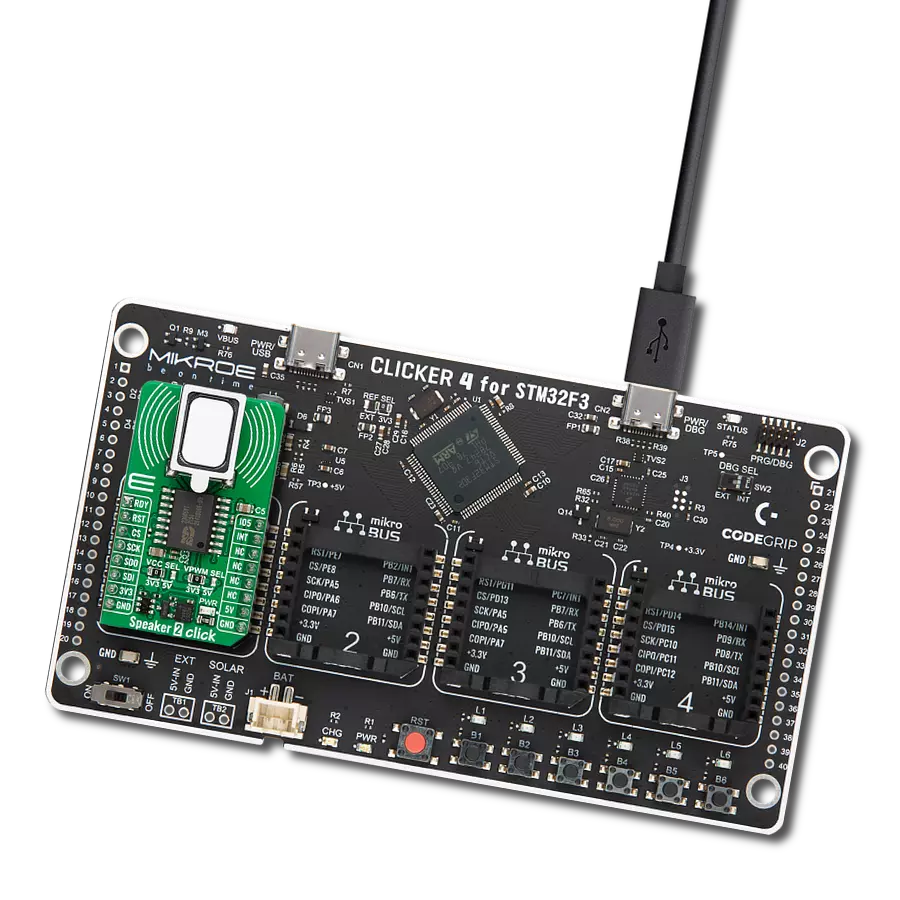
Clicker 4 for STM32F3 is a compact development board designed as a complete solution, you can use it to quickly build your own gadgets with unique functionalities. Featuring a STM32F302VCT6, four mikroBUS™ sockets for Click boards™ connectivity, power managment, and more, it represents a perfect solution for the rapid development of many different types of applications. At its core, there is a STM32F302VCT6 MCU, a powerful microcontroller by STMicroelectronics, based on the high-
performance Arm® Cortex®-M4 32-bit processor core operating at up to 168 MHz frequency. It provides sufficient processing power for the most demanding tasks, allowing Clicker 4 to adapt to any specific application requirements. Besides two 1x20 pin headers, four improved mikroBUS™ sockets represent the most distinctive connectivity feature, allowing access to a huge base of Click boards™, growing on a daily basis. Each section of Clicker 4 is clearly marked, offering an intuitive and clean interface. This makes working with the development
board much simpler and thus, faster. The usability of Clicker 4 doesn’t end with its ability to accelerate the prototyping and application development stages: it is designed as a complete solution which can be implemented directly into any project, with no additional hardware modifications required. Four mounting holes [4.2mm/0.165”] at all four corners allow simple installation by using mounting screws. For most applications, a nice stylish casing is all that is needed to turn the Clicker 4 development board into a fully functional, custom design.

Microcontroller Overview
MCU Card / MCU

Architecture
ARM Cortex-M4
MCU Memory (KB)
256
Silicon Vendor
STMicroelectronics
Pin count
100
RAM (Bytes)
40960
Used MCU Pins
mikroBUS™ mapper
Take a closer look
Click board™ Schematic

Step by step
Project assembly

Start by selecting your development board and Click board™. Begin with the CLICKER 4 for STM32F302VCT6 as your development board.


Track your results in real time
Application Output
1. Application Output - In Debug mode, the 'Application Output' window enables real-time data monitoring, offering direct insight into execution results. Ensure proper data display by configuring the environment correctly using the provided tutorial.

2. UART Terminal - Use the UART Terminal to monitor data transmission via a USB to UART converter, allowing direct communication between the Click board™ and your development system. Configure the baud rate and other serial settings according to your project's requirements to ensure proper functionality. For step-by-step setup instructions, refer to the provided tutorial.

3. Plot Output - The Plot feature offers a powerful way to visualize real-time sensor data, enabling trend analysis, debugging, and comparison of multiple data points. To set it up correctly, follow the provided tutorial, which includes a step-by-step example of using the Plot feature to display Click board™ readings. To use the Plot feature in your code, use the function: plot(*insert_graph_name*, variable_name);. This is a general format, and it is up to the user to replace 'insert_graph_name' with the actual graph name and 'variable_name' with the parameter to be displayed.

Software Support
Library Description
Speaker 2 Click demo application is developed using the NECTO Studio, ensuring compatibility with mikroSDK's open-source libraries and tools. Designed for plug-and-play implementation and testing, the demo is fully compatible with all development, starter, and mikromedia boards featuring a mikroBUS™ socket.
Example Description
This example demonstrates the use of the Speaker 2 Click board. It initializes the board and plays predefined voice messages or sound effects through the speaker module. Supported voices include numbers (ONE to SIX) and sound effects like FAST BEEP.
Key functions:
speaker2_cfg_setup- Config Object Initialization function.speaker2_init- Initialization function.speaker2_default_cfg- Click Default Configuration function.speaker2_play_voice- This function plays a voice at the specified index.speaker2_play_macro- This function executes a macro command at the specified index.speaker2_play_voice_loop- This function plays a voice in a loop for a specified number of iterations.
Application Init
Initializes the logger module, configures the Speaker 2 Click board, and applies the default settings to reset the device, power it up, verify communication, and load an example audio project into the device memory.
Application Task
Sequentially plays predefined voice messages and sound effects from the Speaker 2 Click board while logging the playback status (DONE or ERROR) for each sound.
Open Source
Code example
The complete application code and a ready-to-use project are available through the NECTO Studio Package Manager for direct installation in the NECTO Studio. The application code can also be found on the MIKROE GitHub account.
/*!
 * @file main.c
 * @brief Speaker 2 Click example
 *
 * # Description
 * This example demonstrates the use of the Speaker 2 Click board. It initializes the board
 * and plays predefined voice messages or sound effects through the speaker module.
 * Supported voices include numbers (ONE to SIX) and sound effects like FAST BEEP.
 *
 * The demo application is composed of two sections:
 *
 * ## Application Init
 * Initializes the logger module, configures the Speaker 2 Click board, and applies the
 * default settings to reset the device, power it up, verify communication, and load an example
 * audio project into the device memory.
 *
 * ## Application Task
 * Sequentially plays predefined voice messages and sound effects from the Speaker 2 Click board
 * while logging the playback status (DONE or ERROR) for each sound.
 *
 * @author Stefan Filipovic
 *
 */

#include "board.h"
#include "log.h"
#include "speaker2.h"

static speaker2_t speaker2;
static log_t logger;

void application_init ( void )
{
    log_cfg_t log_cfg;  /**< Logger config object. */
    speaker2_cfg_t speaker2_cfg;  /**< Click config object. */

    /**
     * Logger initialization.
     * Default baud rate: 115200
     * Default log level: LOG_LEVEL_DEBUG
     * @note If USB_UART_RX and USB_UART_TX
     * are defined as HAL_PIN_NC, you will
     * need to define them manually for log to work.
     * See @b LOG_MAP_USB_UART macro definition for detailed explanation.
     */
    LOG_MAP_USB_UART( log_cfg );
    log_init( &logger, &log_cfg );
    log_info( &logger, " Application Init " );

    // Click initialization.
    speaker2_cfg_setup( &speaker2_cfg );
    SPEAKER2_MAP_MIKROBUS( speaker2_cfg, MIKROBUS_1 );
    if ( SPI_MASTER_ERROR == speaker2_init( &speaker2, &speaker2_cfg ) )
    {
        log_error( &logger, " Communication init." );
        for ( ; ; );
    }

    if ( SPEAKER2_ERROR == speaker2_default_cfg ( &speaker2 ) )
    {
        log_error( &logger, " Default configuration." );
        for ( ; ; );
    }

    log_info( &logger, " Application Task " );
}

void application_task ( void )
{
    log_printf ( &logger, " Playing voice ONE: %s\r\n\n", ( char * )
                 ( ( SPEAKER2_OK == speaker2_play_voice ( &speaker2, SPEAKER2_VP9_ONE ) ) ? "DONE" : "ERROR" ) );
    log_printf ( &logger, " Playing voice TWO: %s\r\n\n", ( char * )
                 ( ( SPEAKER2_OK == speaker2_play_voice ( &speaker2, SPEAKER2_VP10_TWO ) ) ? "DONE" : "ERROR" ) );
    log_printf ( &logger, " Playing voice THREE: %s\r\n\n", ( char * )
                 ( ( SPEAKER2_OK == speaker2_play_voice ( &speaker2, SPEAKER2_VP11_THREE ) ) ? "DONE" : "ERROR" ) );
    log_printf ( &logger, " Playing voice FOUR: %s\r\n\n", ( char * )
                 ( ( SPEAKER2_OK == speaker2_play_voice ( &speaker2, SPEAKER2_VP12_FOUR ) ) ? "DONE" : "ERROR" ) );
    log_printf ( &logger, " Playing voice FIVE: %s\r\n\n", ( char * )
                 ( ( SPEAKER2_OK == speaker2_play_voice ( &speaker2, SPEAKER2_VP13_FIVE ) ) ? "DONE" : "ERROR" ) );
    log_printf ( &logger, " Playing voice SIX: %s\r\n\n", ( char * )
                 ( ( SPEAKER2_OK == speaker2_play_voice ( &speaker2, SPEAKER2_VP14_SIX ) ) ? "DONE" : "ERROR" ) );
    log_printf ( &logger, " Playing voice FAST BEEP: %s\r\n\n", ( char * )
                 ( ( SPEAKER2_OK == speaker2_play_voice ( &speaker2, SPEAKER2_VP15_FAST_BEEP ) ) ? "DONE" : "ERROR" ) );
}

int main ( void )
{
    /* Do not remove this line or clock might not be set correctly. */
    #ifdef PREINIT_SUPPORTED
    preinit();
    #endif

    application_init( );

    for ( ; ; )
    {
        application_task( );
    }

    return 0;
}

// ------------------------------------------------------------------------ END
Additional Support
Resources
Category:Speakers