Provide precise estimates of remaining battery charge with LC709204V and PIC32MX470F512H
Fuel gauging solution of 1-cell Lithium-ion/Polymer (Li+) batteries

Published Jan 07, 2025
Click board™
BATT-MON 5 Click
Dev. board
6LoWPAN clicker
Compiler
NECTO Studio
MCU
PIC32MX470F512H
Ensure reliable battery performance with precise fuel gauging and safety monitoring
A
A
Hardware Overview
How does it work?
BATT-MON 5 Click is based on the LC709204V, a 1-cell Lithium-ion/Polymer (Li+) battery fuel gauge from onsemi. This highly efficient fuel gauge monitors battery performance with exceptional accuracy and stability while consuming minimal power, making it a perfect solution for modern portable and battery-powered devices. The LC709204V uses the innovative HG-CVR2 algorithm, a proprietary technology that accurately determines a battery's Relative State of Charge (RSOC). This algorithm ensures reliable RSOC readings even under varying and challenging conditions such as fluctuating temperatures, different load demands, aging of the battery, and self-discharge rates. With precise RSOC measurement, the LC709204V optimizes battery usage, extending the operating time of devices like wearables, PDAs, USB-related systems, and configurations such as 1-series N-parallel battery systems. One of the standout features of the
LC709204V is its ease of integration. To begin operation, the HG-CVR2 algorithm requires only a few simple parameter configurations upon battery insertion. This significantly reduces development complexity and allows for rapid deployment in various applications. In addition, the device offers State of Health (SOH) reporting, giving insights into the overall condition and longevity of the battery. This Click board™ is designed in a unique format supporting the newly introduced MIKROE feature called "Click Snap." Unlike the standardized version of Click boards, this feature allows the main IC area to become movable by breaking the PCB, opening up many new possibilities for implementation. Thanks to the Snap feature, the LC709204V can operate autonomously by accessing its signals directly on the pins marked 1-8. Additionally, the Snap part includes a specified and fixed screw hole position, enabling users to secure the Snap board in their desired location.
BATT-MON 5 Click communicates with the host MCU via a standard I2C interface, supporting clock speeds of up to 400kHz for fast and efficient data exchange. To ensure safety and reliability, the board includes an alert interrupt (ALR) pin, activated whenever critical conditions are detected, such as low cell voltage, abnormal temperature, or low Relative State of Charge (RSOC). This integrated alarm functionality provides timely alerts to users, helping to prevent potential issues like over-discharge or unsafe operating conditions, thereby enhancing overall battery safety. This Click board™ can operate with either 3.3V or 5V logic voltage levels selected via the VCC SEL jumper. This way, both 3.3V and 5V capable MCUs can use the communication lines properly. Also, this Click board™ comes equipped with a library containing easy-to-use functions and an example code that can be used as a reference for further development.

Features overview
Development board
6LoWPAN Clicker is a compact starter development board that brings the flexibility of add-on Click boards™ to your favorite microcontroller, making it a perfect starter kit for implementing your ideas. It comes with an onboard 32-bit PIC microcontroller, the PIC32MX470F512H from Microchip, a USB connector, LED indicators, buttons, a mikroProg connector, and a header for interfacing with external electronics. Along with this microcontroller, the board also contains a 2.4GHz ISM band transceiver, allowing you to add wireless communication to your target application. Its compact design provides a fluid and immersive working experience, allowing access anywhere
and under any circumstances. Each part of the 6LoWPAN Clicker development kit contains the components necessary for the most efficient operation of the same board. In addition to the possibility of choosing the 6LoWPAN Clicker programming method, using USB HID mikroBootloader, or through an external mikroProg connector for PIC, dsPIC, or PIC32 programmer, the Clicker board also includes a clean and regulated power supply module for the development kit. The USB Micro-B connection can provide up to 500mA of current for the Clicker board, which is more than enough to operate all onboard and additional modules, or it can power
over two standard AA batteries. All communication methods that mikroBUS™ itself supports are on this board, including the well-established mikroBUS™ socket, reset button, and several buttons and LED indicators. 6LoWPAN Clicker is an integral part of the Mikroe ecosystem, allowing you to create a new application in minutes. Natively supported by Mikroe software tools, it covers many aspects of prototyping thanks to a considerable number of different Click boards™ (over a thousand boards), the number of which is growing every day.

Microcontroller Overview
MCU Card / MCU

Architecture
PIC32
MCU Memory (KB)
512
Silicon Vendor
Microchip
Pin count
64
RAM (Bytes)
131072
You complete me!
Accessories
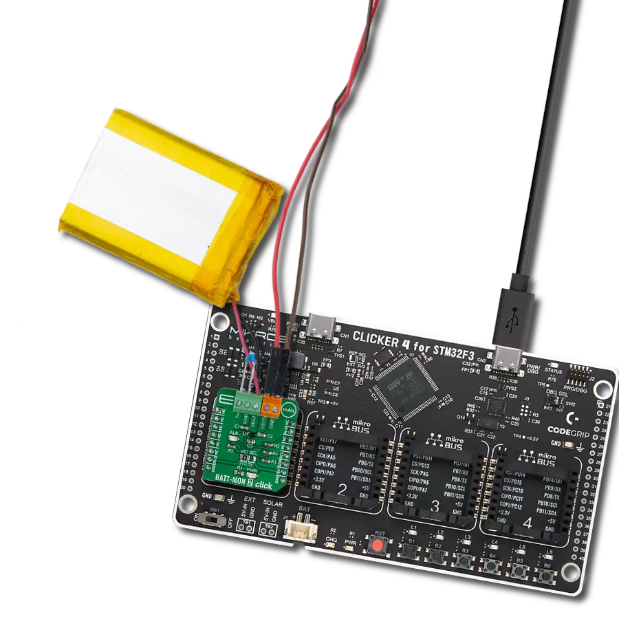
Li-Polymer Battery is the ideal solution for devices that demand a dependable and long-lasting power supply while emphasizing mobility. Its compatibility with mikromedia boards ensures easy integration without additional modifications. With a voltage output of 3.7V, the battery meets the standard requirements of many electronic devices. Additionally, boasting a capacity of 2000mAh, it can store a substantial amount of energy, providing sustained power for extended periods. This feature minimizes the need for frequent recharging or replacement. Overall, the Li-Polymer Battery is a reliable and autonomous power source, ideally suited for devices requiring a stable and enduring energy solution.

Used MCU Pins
mikroBUS™ mapper
Take a closer look
Click board™ Schematic

Step by step
Project assembly

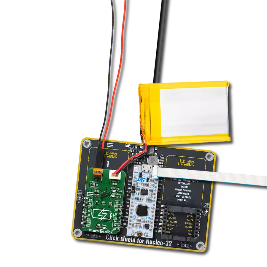
Start by selecting your development board and Click board™. Begin with the 6LoWPAN clicker as your development board.


Track your results in real time
Application Output
1. Application Output - In Debug mode, the 'Application Output' window enables real-time data monitoring, offering direct insight into execution results. Ensure proper data display by configuring the environment correctly using the provided tutorial.

2. UART Terminal - Use the UART Terminal to monitor data transmission via a USB to UART converter, allowing direct communication between the Click board™ and your development system. Configure the baud rate and other serial settings according to your project's requirements to ensure proper functionality. For step-by-step setup instructions, refer to the provided tutorial.

3. Plot Output - The Plot feature offers a powerful way to visualize real-time sensor data, enabling trend analysis, debugging, and comparison of multiple data points. To set it up correctly, follow the provided tutorial, which includes a step-by-step example of using the Plot feature to display Click board™ readings. To use the Plot feature in your code, use the function: plot(*insert_graph_name*, variable_name);. This is a general format, and it is up to the user to replace 'insert_graph_name' with the actual graph name and 'variable_name' with the parameter to be displayed.

Software Support
Library Description
BATT-MON 5 Click demo application is developed using the NECTO Studio, ensuring compatibility with mikroSDK's open-source libraries and tools. Designed for plug-and-play implementation and testing, the demo is fully compatible with all development, starter, and mikromedia boards featuring a mikroBUS™ socket.
Example Description
This example demonstrates the use of BATT-MON 5 Click board by reading the battery cell voltage and the relative state of charge (RSOC).
Key functions:
battmon5_cfg_setup- Config Object Initialization function.battmon5_init- Initialization function.battmon5_default_cfg- Click Default Configuration function.battmon5_write_reg- This function writes a data word starting to the selected register by using I2C serial interface.battmon5_read_reg- This function reads a data word from the selected register by using I2C serial interface.battmon5_get_alarm_pin- This function returns the ALARM pin logic state.
Application Init
Initializes the driver and performs the Click default configuration.
Application Task
Reads the battery cell voltage and the relative state of charge (RSOC) and displays the results on the USB UART approximately once per second.
Open Source
Code example
The complete application code and a ready-to-use project are available through the NECTO Studio Package Manager for direct installation in the NECTO Studio. The application code can also be found on the MIKROE GitHub account.
/*!
 * @file main.c
 * @brief BATT-MON 5 Click example
 *
 * # Description
 * This example demonstrates the use of BATT-MON 5 Click board by reading
 * the battery cell voltage and the relative state of charge (RSOC).
 *
 * The demo application is composed of two sections :
 *
 * ## Application Init
 * Initializes the driver and performs the Click default configuration.
 *
 * ## Application Task
 * Reads the battery cell voltage and the relative state of charge (RSOC) and
 * displays the results on the USB UART approximately once per second.
 *
 * @note
 * For the communication with the Click board to work, the battery needs to be connected.
 * The Click board is configured by default for a 2000 mAh battery pack capacity.
 *
 * @author Stefan Filipovic
 *
 */

#include "board.h"
#include "log.h"
#include "battmon5.h"

static battmon5_t battmon5;
static log_t logger;

void application_init ( void )
{
    log_cfg_t log_cfg;  /**< Logger config object. */
    battmon5_cfg_t battmon5_cfg;  /**< Click config object. */

    /**
     * Logger initialization.
     * Default baud rate: 115200
     * Default log level: LOG_LEVEL_DEBUG
     * @note If USB_UART_RX and USB_UART_TX
     * are defined as HAL_PIN_NC, you will
     * need to define them manually for log to work.
     * See @b LOG_MAP_USB_UART macro definition for detailed explanation.
     */
    LOG_MAP_USB_UART( log_cfg );
    log_init( &logger, &log_cfg );
    log_info( &logger, " Application Init " );

    // Click initialization.
    battmon5_cfg_setup( &battmon5_cfg );
    BATTMON5_MAP_MIKROBUS( battmon5_cfg, MIKROBUS_1 );
    if ( I2C_MASTER_ERROR == battmon5_init( &battmon5, &battmon5_cfg ) )
    {
        log_error( &logger, " Communication init." );
        for ( ; ; );
    }

    if ( BATTMON5_ERROR == battmon5_default_cfg ( &battmon5 ) )
    {
        log_error( &logger, " Default configuration." );
        for ( ; ; );
    }

    log_info( &logger, " Application Task " );
}

void application_task ( void )
{
    uint16_t voltage = 0;
    uint16_t rsoc = 0;
    if ( BATTMON5_OK == battmon5_read_reg ( &battmon5, BATTMON5_REG_CELL_V, &voltage ) )
    {
        log_printf ( &logger, " Voltage: %u mV\r\n", voltage ); // Battery Cell Voltage
    }
    if ( BATTMON5_OK == battmon5_read_reg ( &battmon5, BATTMON5_REG_RSOC, &rsoc ) )
    {
        log_printf ( &logger, " RSOC: %u %%\r\n\n", rsoc ); // Relative State Of Charge
    }
    Delay_ms ( 1000 );
}

int main ( void )
{
    /* Do not remove this line or clock might not be set correctly. */
    #ifdef PREINIT_SUPPORTED
    preinit();
    #endif

    application_init( );

    for ( ; ; )
    {
        application_task( );
    }

    return 0;
}

// ------------------------------------------------------------------------ END
Additional Support
Resources
Category:Battery charger