Creates dynamic red visual outputs with MAX7129 and STM32G474RE
Serial 8x8 red LED matrix display

Published Mar 09, 2025
Click board™
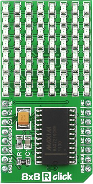
8x8 R Click
Dev. board
Nucleo 64 with STM32G474RE MCU
Compiler
NECTO Studio
MCU
STM32G474RE
Create dynamic red LED matrix display perfect for indicators, animations, and real-time visual feedback
A
A
Hardware Overview
How does it work?
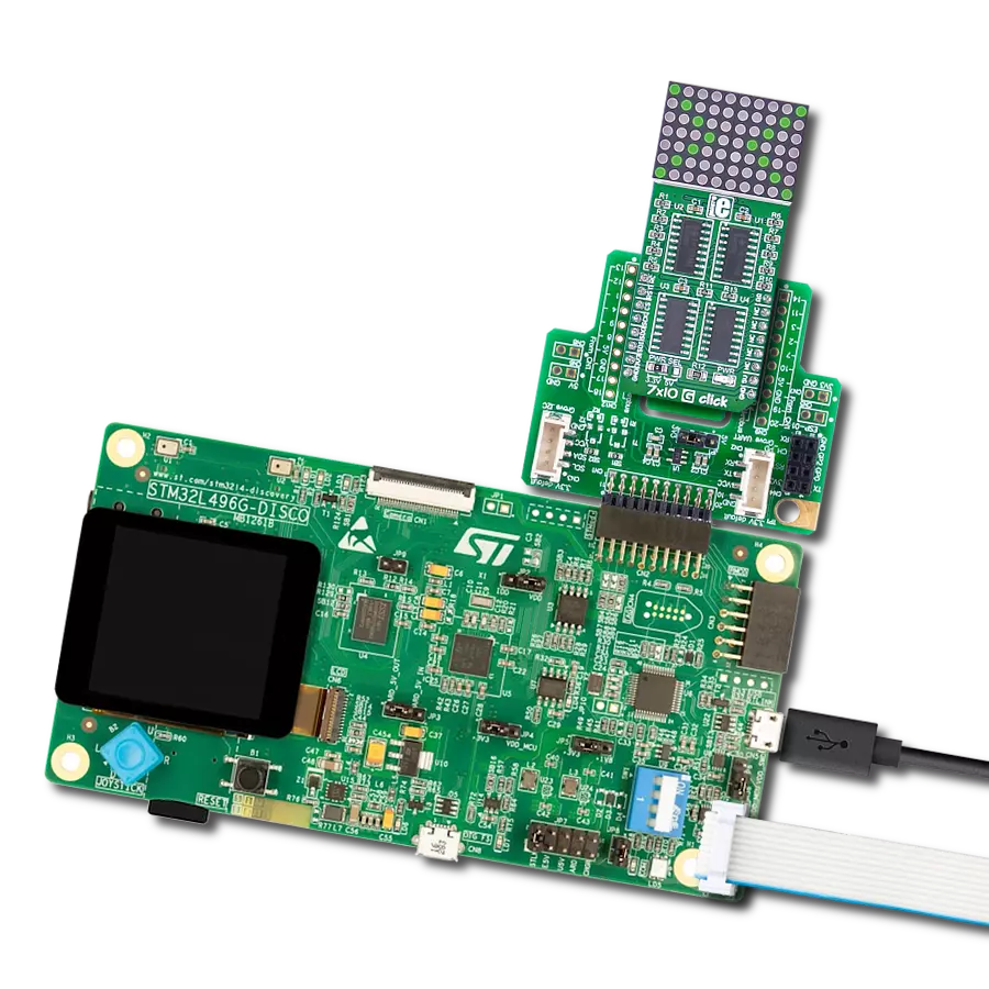
8x8 R Click is a compact 64 red LED matrix display Click board™, featuring a MAX7129 LED driver for precise control. It enables independent LED control, 16-step digital brightness adjustment, and glitch-free startup by blanking the display on power-up. With a fast SPI interface, 8x8 R Click ensures smooth data transmission and quick
response. The MAX7129 IC integrates 8x8 RAM storage, a 16-bit data shifter, a constant current source, and a PWM intensity control register, allowing efficient LED matrix operation. Designed for easy integration, the board requires only one external resistor for current control, simplifying the design. The 800Hz refresh rate ensures flicker-free
performance, while daisy-chaining support allows expansion with multiple modules. Ideal for LED matrix displays, bar graphs, and panel meters, 8x8 R Click provides a reliable solution for visual output in embedded applications.

Features overview
Development board
Nucleo-64 with STM32G474R MCU offers a cost-effective and adaptable platform for developers to explore new ideas and prototype their designs. This board harnesses the versatility of the STM32 microcontroller, enabling users to select the optimal balance of performance and power consumption for their projects. It accommodates the STM32 microcontroller in the LQFP64 package and includes essential components such as a user LED, which doubles as an ARDUINO® signal, alongside user and reset push-buttons, and a 32.768kHz crystal oscillator for precise timing operations. Designed with expansion and flexibility in mind, the Nucleo-64 board features an ARDUINO® Uno V3 expansion connector and ST morpho extension pin
headers, granting complete access to the STM32's I/Os for comprehensive project integration. Power supply options are adaptable, supporting ST-LINK USB VBUS or external power sources, ensuring adaptability in various development environments. The board also has an on-board ST-LINK debugger/programmer with USB re-enumeration capability, simplifying the programming and debugging process. Moreover, the board is designed to simplify advanced development with its external SMPS for efficient Vcore logic supply, support for USB Device full speed or USB SNK/UFP full speed, and built-in cryptographic features, enhancing both the power efficiency and security of projects. Additional connectivity is
provided through dedicated connectors for external SMPS experimentation, a USB connector for the ST-LINK, and a MIPI® debug connector, expanding the possibilities for hardware interfacing and experimentation. Developers will find extensive support through comprehensive free software libraries and examples, courtesy of the STM32Cube MCU Package. This, combined with compatibility with a wide array of Integrated Development Environments (IDEs), including IAR Embedded Workbench®, MDK-ARM, and STM32CubeIDE, ensures a smooth and efficient development experience, allowing users to fully leverage the capabilities of the Nucleo-64 board in their projects.

Microcontroller Overview
MCU Card / MCU

Architecture
ARM Cortex-M4
MCU Memory (KB)
512
Silicon Vendor
STMicroelectronics
Pin count
64
RAM (Bytes)
128k
You complete me!
Accessories
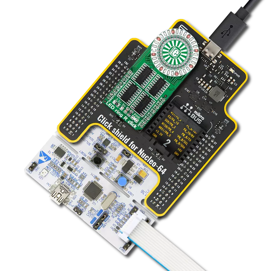
Click Shield for Nucleo-64 comes equipped with two proprietary mikroBUS™ sockets, allowing all the Click board™ devices to be interfaced with the STM32 Nucleo-64 board with no effort. This way, Mikroe allows its users to add any functionality from our ever-growing range of Click boards™, such as WiFi, GSM, GPS, Bluetooth, ZigBee, environmental sensors, LEDs, speech recognition, motor control, movement sensors, and many more. More than 1537 Click boards™, which can be stacked and integrated, are at your disposal. The STM32 Nucleo-64 boards are based on the microcontrollers in 64-pin packages, a 32-bit MCU with an ARM Cortex M4 processor operating at 84MHz, 512Kb Flash, and 96KB SRAM, divided into two regions where the top section represents the ST-Link/V2 debugger and programmer while the bottom section of the board is an actual development board. These boards are controlled and powered conveniently through a USB connection to program and efficiently debug the Nucleo-64 board out of the box, with an additional USB cable connected to the USB mini port on the board. Most of the STM32 microcontroller pins are brought to the IO pins on the left and right edge of the board, which are then connected to two existing mikroBUS™ sockets. This Click Shield also has several switches that perform functions such as selecting the logic levels of analog signals on mikroBUS™ sockets and selecting logic voltage levels of the mikroBUS™ sockets themselves. Besides, the user is offered the possibility of using any Click board™ with the help of existing bidirectional level-shifting voltage translators, regardless of whether the Click board™ operates at a 3.3V or 5V logic voltage level. Once you connect the STM32 Nucleo-64 board with our Click Shield for Nucleo-64, you can access hundreds of Click boards™, working with 3.3V or 5V logic voltage levels.

Used MCU Pins
mikroBUS™ mapper
Take a closer look
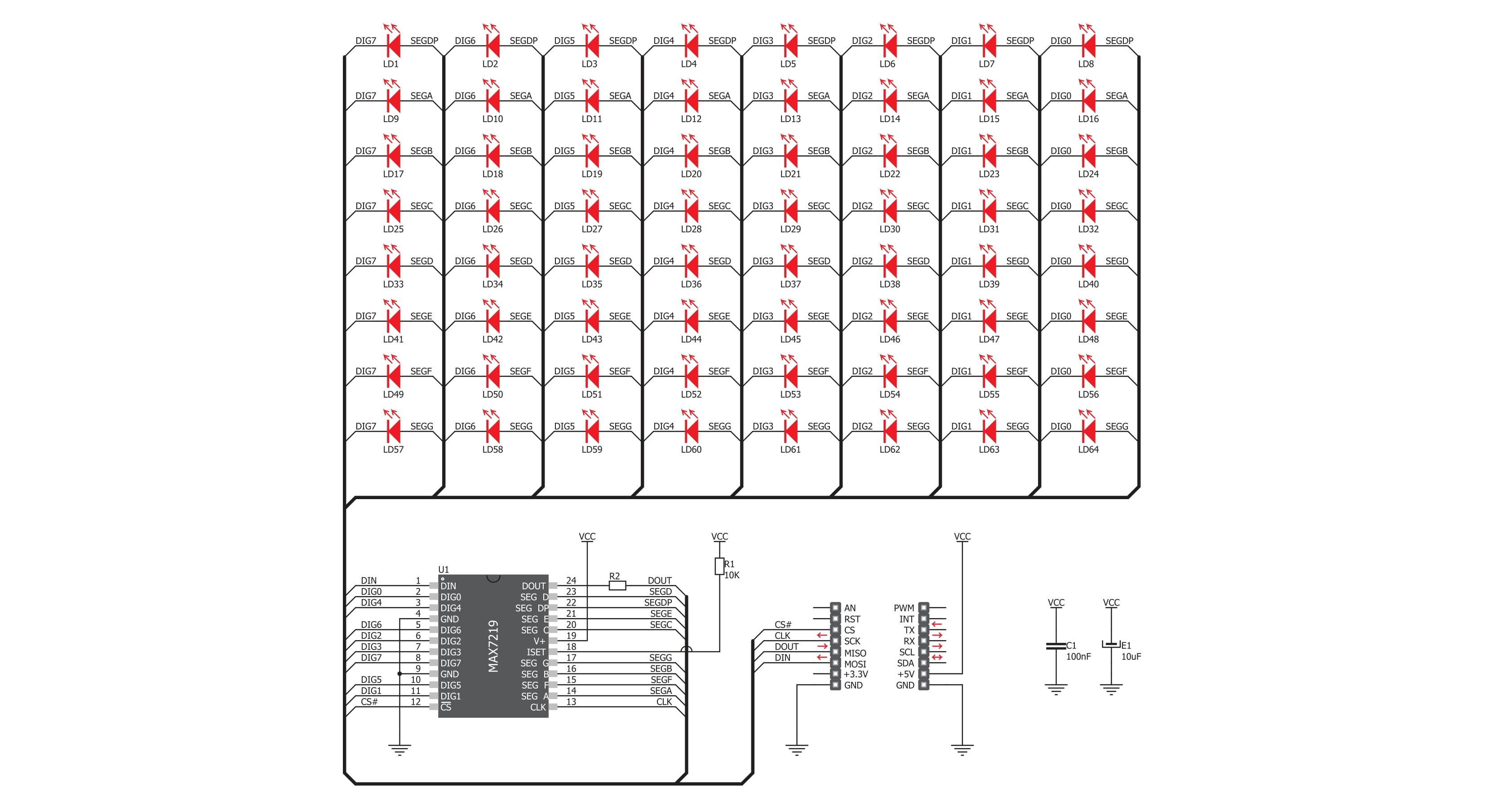
Click board™ Schematic
Step by step
Project assembly
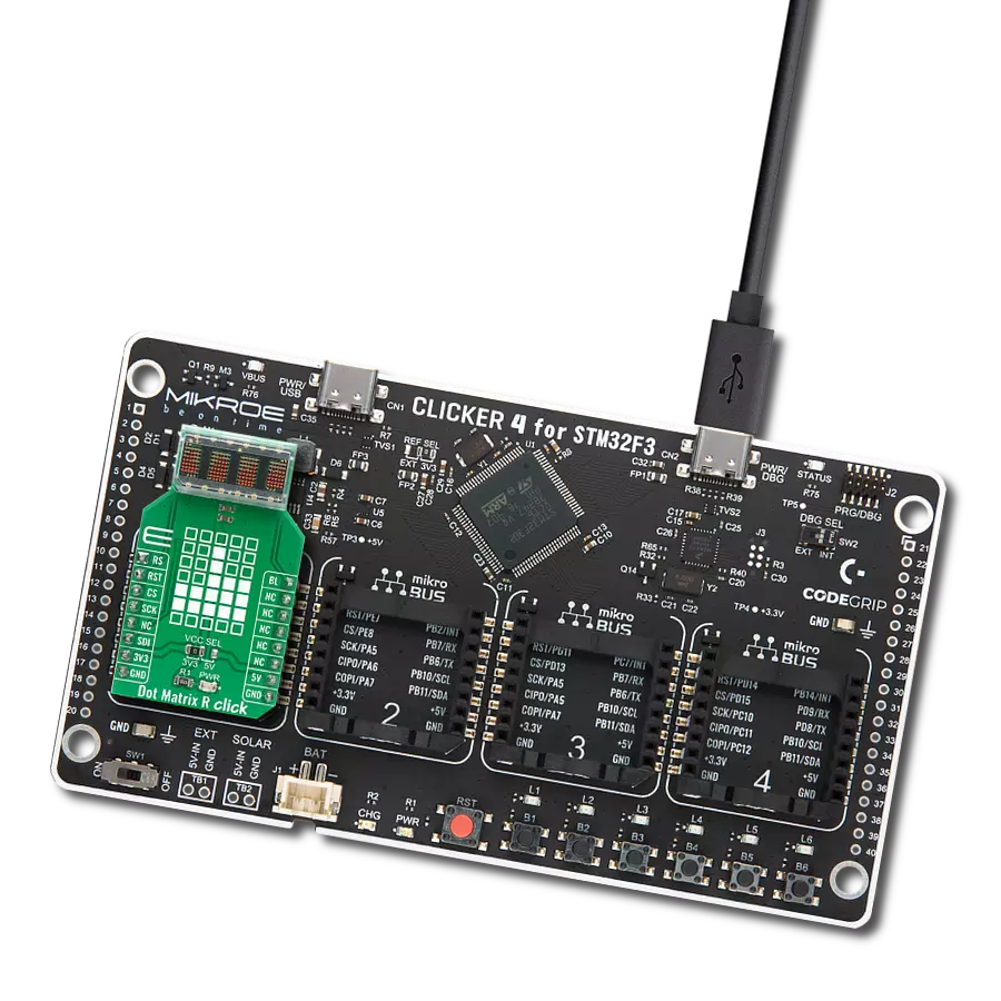
Start by selecting your development board and Click board™. Begin with the Nucleo 64 with STM32G474RE MCU as your development board.


Track your results in real time
Application Output
1. Application Output - In Debug mode, the 'Application Output' window enables real-time data monitoring, offering direct insight into execution results. Ensure proper data display by configuring the environment correctly using the provided tutorial.

2. UART Terminal - Use the UART Terminal to monitor data transmission via a USB to UART converter, allowing direct communication between the Click board™ and your development system. Configure the baud rate and other serial settings according to your project's requirements to ensure proper functionality. For step-by-step setup instructions, refer to the provided tutorial.

3. Plot Output - The Plot feature offers a powerful way to visualize real-time sensor data, enabling trend analysis, debugging, and comparison of multiple data points. To set it up correctly, follow the provided tutorial, which includes a step-by-step example of using the Plot feature to display Click board™ readings. To use the Plot feature in your code, use the function: plot(*insert_graph_name*, variable_name);. This is a general format, and it is up to the user to replace 'insert_graph_name' with the actual graph name and 'variable_name' with the parameter to be displayed.

Software Support
Library Description
8x8 R Click demo application is developed using the NECTO Studio, ensuring compatibility with mikroSDK's open-source libraries and tools. Designed for plug-and-play implementation and testing, the demo is fully compatible with all development, starter, and mikromedia boards featuring a mikroBUS™ socket.
Example Description
This demo example shows a drawing of Image, new create string and character on the screen.
Key functions:
c8x8r_cfg_setup- Config Object Initialization function.c8x8r_init- Initialization function.c8x8r_default_cfg- Click Default Configuration function.c8x8r_write_cmd- This function writes a desired number of data bytes starting from the selected register by using SPI serial interface.c8x8r_display_refresh- The function switches off all LEDs.c8x8r_display_byte- This function displayes one character to the display.
Application Init
Configuring Clicks and log objects. Settings the Click in the default configuration.
Application Task
Shows one byte, then scrolls the string and image, every 1 sec.
Open Source
Code example
The complete application code and a ready-to-use project are available through the NECTO Studio Package Manager for direct installation in the NECTO Studio. The application code can also be found on the MIKROE GitHub account.
/*!
 * @file main.c
 * @brief 8x8 R Click example
 *
 * # Description
 * This demo example shows a drawing of Image, new create string and character on the screen.
 *
 * The demo application is composed of two sections :
 *
 * ## Application Init
 * Configuring Clicks and log objects.
 * Settings the Click in the default configuration.
 *
 * ## Application Task
 * Shows one byte, then scrolls the string and image, every 1 sec.
 *
 * @author Stefan Ilic
 *
 */

#include "board.h"
#include "log.h"
#include "c8x8r.h"

static c8x8r_t c8x8r;
static log_t logger;

uint8_t demo_string[ 11 ] = { ' ', '-', 'M', 'i', 'k', 'r', 'o', 'E', '-', ' ', 0 };
uint8_t demo_img_on[ 8 ] = { 0x08, 0x1c, 0x36, 0x22, 0x08, 0x1c, 0x36, 0x22 };
uint8_t demo_img_off[ 8 ] = { 0xf7, 0xe3, 0xc9, 0xdd, 0xf7, 0xe3, 0xc9, 0xdd };
char demo_char = 'A';

void application_init ( void ) {
    log_cfg_t log_cfg;  /**< Logger config object. */
    c8x8r_cfg_t c8x8r_cfg;  /**< Click config object. */

    /**
     * Logger initialization.
     * Default baud rate: 115200
     * Default log level: LOG_LEVEL_DEBUG
     * @note If USB_UART_RX and USB_UART_TX
     * are defined as HAL_PIN_NC, you will
     * need to define them manually for log to work.
     * See @b LOG_MAP_USB_UART macro definition for detailed explanation.
     */
    LOG_MAP_USB_UART( log_cfg );
    log_init( &logger, &log_cfg );
    log_info( &logger, " Application Init " );

    // Click initialization.

    c8x8r_cfg_setup( &c8x8r_cfg );
    C8X8R_MAP_MIKROBUS( c8x8r_cfg, MIKROBUS_1 );
    err_t init_flag  = c8x8r_init( &c8x8r, &c8x8r_cfg );
    if ( init_flag == SPI_MASTER_ERROR ) {
        log_info( &logger, " Application Init Error. " );
        log_info( &logger, " Please, run program again... " );

        for ( ; ; );
    }

    c8x8r_default_cfg ( &c8x8r );
    log_info( &logger, " Application Task " );
    Delay_ms ( 1000 );
}

void application_task ( void ) {
    c8x8r_display_byte( &c8x8r, demo_char );
    Delay_ms ( 1000 );

    c8x8r_display_string( &c8x8r, &demo_string[ 0 ] );
    Delay_ms ( 1000 );

    c8x8r_display_image( &c8x8r, &demo_img_on[ 0 ] );
    Delay_ms ( 1000 );

    c8x8r_display_image( &c8x8r, &demo_img_off[ 0 ] );
    Delay_ms ( 1000 );
}

int main ( void )
{
    /* Do not remove this line or clock might not be set correctly. */
    #ifdef PREINIT_SUPPORTED
    preinit();
    #endif

    application_init( );

    for ( ; ; )
    {
        application_task( );
    }

    return 0;
}

// ------------------------------------------------------------------------ END
Additional Support
Resources
Category:LED Matrix