Monitor indoor air quality with RRH46410 and PIC32MX470F512H
Total volatile organic compounds (TVOC), indoor air quality (IAQ), and estimated carbon dioxide (eCO2) sensing solution

Published Dec 31, 2024
Click board™
Air Quality 12 Click
Dev. board
6LoWPAN clicker
Compiler
NECTO Studio
MCU
PIC32MX470F512H
Indoor air quality monitor based on AI-enhanced gas sensing technology perfect for homes, offices, HVAC systems, and air purifiers
A
A
Hardware Overview
How does it work?
Air Quality 12 Click is based on the RRH46410, a digital gas sensor module from Renesas designed for monitoring indoor air quality. This module integrates advanced sensing technology to detect and measure total volatile organic compounds (TVOC), indoor air quality (IAQ), and estimated carbon dioxide levels (eCO2) with precision and reliability. Tailored for indoor air monitoring applications, this sensor module combines a MEMS gas sensing element, a CMOS signal conditioning IC, and an onboard microcontroller, offering a complete, self-contained gas detection solution. Thanks to its low operating power consumption and multiple operational methods, this solution is ideally suited for applications such as indoor air quality monitoring, ensuring healthy environments in homes, offices, and public buildings, and detection of hazardous materials and harmful fumes, including those from construction materials, and automation of air quality-based devices. The RRH46410's MEMS gas sensing element incorporates a heater on a silicon-based structure and a metal oxide (MOx) chemiresistor, capable of
detecting changes in conductivity caused by gas concentrations. The module's signal conditioner regulates the sensor temperature and processes MOx conductivity measurements, while the integrated microcontroller generates a calibrated digital output, eliminating the need for complex data processing on the user's host MCU. The RRH46410 stands out for its intelligent design, leveraging artificial intelligence (AI) and a machine-learning algorithm to produce accurate air quality measurements. It can detect TVOC contaminants based on established international indoor air quality standards while responding effectively, though not selectively, to hydrogen (H₂) within the parts-per-million range. Its fast response time, measured in seconds, ensures near-instantaneous readings without requiring direct airflow onto the sensor. However, while it can detect gases like carbon monoxide (CO), it is not approved for safety-critical applications and should not be relied upon for life-saving use cases. This Click board™ supports both UART and I2C interfaces for communication with the host MCU. The UART interface operates at a
default baud rate of 115200bps, enabling efficient data transmission and exchange, while the I2C interface supports clock frequencies of up to 400kHz for flexible integration with various systems. In addition to the interface pins, the board includes other control pins such as the RST pin for resetting the module, the INT pin for real-time alerts (set HIGH when data is available and LOW after data is read), and the GP1 pin, which controls the red GP1 LED. This user-configurable LED serves as a visual indicator for various scenarios based on the user's needs. The board also features two unpopulated pins labeled GP3 and GP4, which are general-purpose I/O pins configured as always-inputs and lacking internal pull-ups, providing additional versatility for custom applications. This Click board™ can be operated only with a 3.3V logic voltage level. The board must perform appropriate logic voltage level conversion before using MCUs with different logic levels. It also comes equipped with a library containing functions and example code that can be used as a reference for further development.

Features overview
Development board
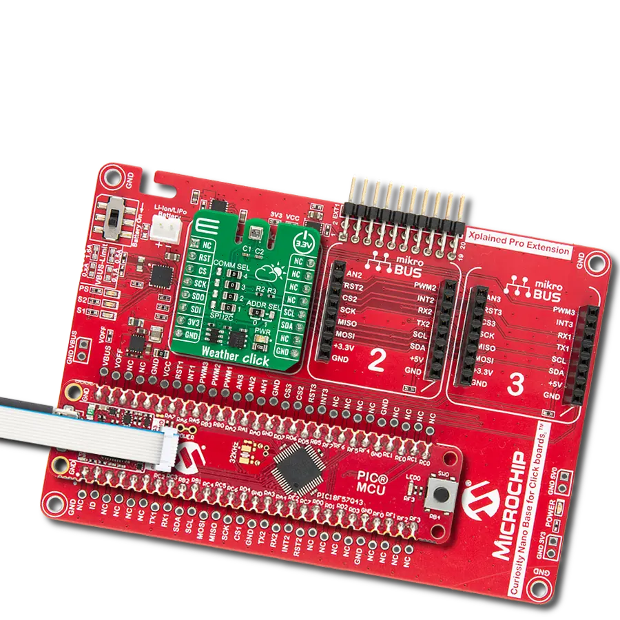
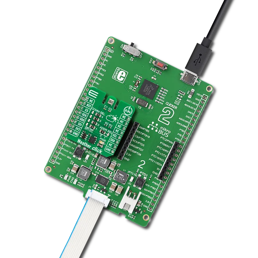
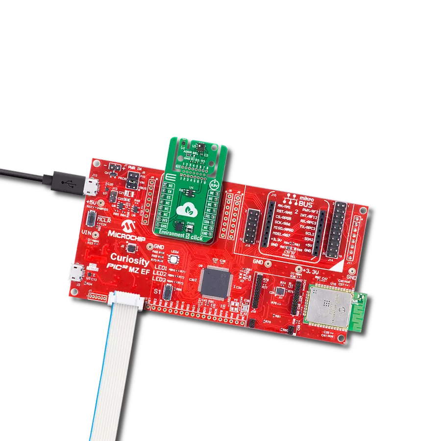
6LoWPAN Clicker is a compact starter development board that brings the flexibility of add-on Click boards™ to your favorite microcontroller, making it a perfect starter kit for implementing your ideas. It comes with an onboard 32-bit PIC microcontroller, the PIC32MX470F512H from Microchip, a USB connector, LED indicators, buttons, a mikroProg connector, and a header for interfacing with external electronics. Along with this microcontroller, the board also contains a 2.4GHz ISM band transceiver, allowing you to add wireless communication to your target application. Its compact design provides a fluid and immersive working experience, allowing access anywhere
and under any circumstances. Each part of the 6LoWPAN Clicker development kit contains the components necessary for the most efficient operation of the same board. In addition to the possibility of choosing the 6LoWPAN Clicker programming method, using USB HID mikroBootloader, or through an external mikroProg connector for PIC, dsPIC, or PIC32 programmer, the Clicker board also includes a clean and regulated power supply module for the development kit. The USB Micro-B connection can provide up to 500mA of current for the Clicker board, which is more than enough to operate all onboard and additional modules, or it can power
over two standard AA batteries. All communication methods that mikroBUS™ itself supports are on this board, including the well-established mikroBUS™ socket, reset button, and several buttons and LED indicators. 6LoWPAN Clicker is an integral part of the Mikroe ecosystem, allowing you to create a new application in minutes. Natively supported by Mikroe software tools, it covers many aspects of prototyping thanks to a considerable number of different Click boards™ (over a thousand boards), the number of which is growing every day.

Microcontroller Overview
MCU Card / MCU

Architecture
PIC32
MCU Memory (KB)
512
Silicon Vendor
Microchip
Pin count
64
RAM (Bytes)
131072
Used MCU Pins
mikroBUS™ mapper
Take a closer look
Click board™ Schematic

Step by step
Project assembly

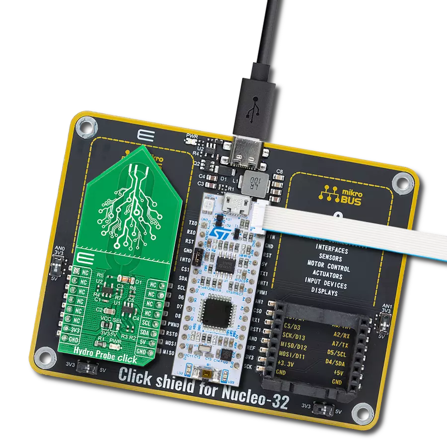
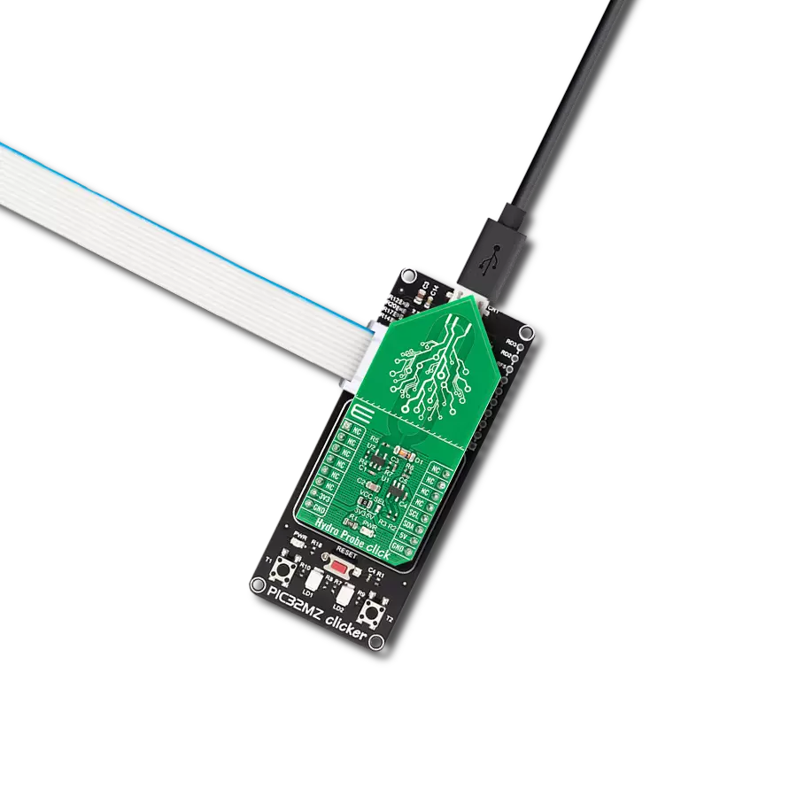
Start by selecting your development board and Click board™. Begin with the 6LoWPAN clicker as your development board.


Software Support
Library Description
This library contains API for Air Quality 12 Click driver.
Key functions:
airquality12_get_sensor_info- This function reads the device product ID, firmware version, and tracking number.airquality12_get_int_pin- This function returns the INT pin logic state.airquality12_get_measurement- This function reads the sensor measurement results.
Open Source
Code example
The complete application code and a ready-to-use project are available through the NECTO Studio Package Manager for direct installation in the NECTO Studio. The application code can also be found on the MIKROE GitHub account.
/*!
 * @file main.c
 * @brief Air Quality 12 Click example
 *
 * # Description
 * This example demonstrates the use of Air Quality 12 Click board by reading the
 * IAQ 2nd Gen measurements and displays the results on the USB UART.
 *
 * The demo application is composed of two sections :
 *
 * ## Application Init
 * Initializes the driver and configures the Click board to the default configuration.
 * Then it reads the sensor product ID, firmware version, and the 48-bit tracking number.
 *
 * ## Application Task
 * Checks the data ready interrupt pin and then reads the IAQ 2nd Gen measurements
 * and displays the results on the USB UART. The GP1 LED turns ON during the data reading.
 * The data sample rate is set to 3 seconds for the IAQ 2nd Gen operating mode, and the first
 * 100 samples upon startup should be ignored since the sensor is in the warm-up phase.
 *
 * @author Stefan Filipovic
 *
 */

#include "board.h"
#include "log.h"
#include "airquality12.h"

static airquality12_t airquality12;
static log_t logger;

void application_init ( void )
{
    log_cfg_t log_cfg;  /**< Logger config object. */
    airquality12_cfg_t airquality12_cfg;  /**< Click config object. */

    /**
     * Logger initialization.
     * Default baud rate: 115200
     * Default log level: LOG_LEVEL_DEBUG
     * @note If USB_UART_RX and USB_UART_TX
     * are defined as HAL_PIN_NC, you will
     * need to define them manually for log to work.
     * See @b LOG_MAP_USB_UART macro definition for detailed explanation.
     */
    LOG_MAP_USB_UART( log_cfg );
    log_init( &logger, &log_cfg );
    log_info( &logger, " Application Init " );

    // Click initialization.
    airquality12_cfg_setup( &airquality12_cfg );
    AIRQUALITY12_MAP_MIKROBUS( airquality12_cfg, MIKROBUS_1 );
    if ( AIRQUALITY12_OK != airquality12_init( &airquality12, &airquality12_cfg ) )
    {
        log_error( &logger, " Communication init." );
        for ( ; ; );
    }

    if ( AIRQUALITY12_ERROR == airquality12_default_cfg ( &airquality12 ) )
    {
        log_error( &logger, " Default configuration." );
        for ( ; ; );
    }

    airquality12_info_t info;
    if ( AIRQUALITY12_OK == airquality12_get_sensor_info ( &airquality12, &info ) )
    {
        log_printf( &logger, " ---- Sensor info ----\r\n" );
        log_printf( &logger, " Product ID: 0x%.4X\r\n", info.product_id );
        log_printf( &logger, " FW version: %u.%u.%u\r\n", ( uint16_t ) info.fw_ver_major,
                                                          ( uint16_t ) info.fw_ver_minor,
                                                          ( uint16_t ) info.fw_ver_patch );
        log_printf( &logger, " Tracking number: 0x%.2X%.2X%.2X%.2X%.2X%.2X\r\n",
                    ( uint16_t ) info.tracking_num[ 5 ], ( uint16_t ) info.tracking_num[ 4 ],
                    ( uint16_t ) info.tracking_num[ 3 ], ( uint16_t ) info.tracking_num[ 2 ],
                    ( uint16_t ) info.tracking_num[ 1 ], ( uint16_t ) info.tracking_num[ 0 ] );
        log_printf( &logger, " ---------------------\r\n" );
    }

    log_info( &logger, " Application Task " );
}

void application_task ( void )
{
    airquality12_results_t results = { 0 };

    if ( airquality12_get_int_pin ( &airquality12 ) )
    {
        airquality12_set_gp1_pin ( &airquality12, 1 );
        if ( AIRQUALITY12_OK == airquality12_get_measurement ( &airquality12, &results ) )
        {
            log_printf ( &logger, " Sample number: %u\r\n", ( uint16_t ) results.sample_num );
            log_printf ( &logger, " IAQ: %.1f\r\n", results.iaq );
            log_printf ( &logger, " TVOC: %.2f mg/m^3\r\n", results.tvoc );
            log_printf ( &logger, " ETOH: %.2f ppm\r\n", results.etoh );
            log_printf ( &logger, " ECO2: %u ppm\r\n", results.eco2 );
            log_printf ( &logger, " rel_IAQ: %u\r\n\n", results.rel_iaq );
        }
        airquality12_set_gp1_pin ( &airquality12, 0 );
    }
}

int main ( void )
{
    /* Do not remove this line or clock might not be set correctly. */
    #ifdef PREINIT_SUPPORTED
    preinit();
    #endif

    application_init( );

    for ( ; ; )
    {
        application_task( );
    }

    return 0;
}

// ------------------------------------------------------------------------ END
Additional Support
Resources
Category:Environmental