Enhance your indoor air quality monitoring with SHT40-BD1B, STC31-C, and MK64FN1M0VDC12
Precise environmental sensing for smarter, healthier spaces!

Published Apr 01, 2025
Click board™
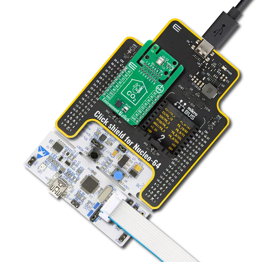
Environment 5 Click
Dev. board
Clicker 2 for Kinetis
Compiler
NECTO Studio
MCU
MK64FN1M0VDC12
Ensure reliable data (temperature, humidity, and CO₂ measurements) for your environmental monitoring needs
A
A
Hardware Overview
How does it work?
Environment 5 Click combines two high-performance sensors from Sensirion: the SHT40-BD1B digital humidity and temperature sensor and the STC31-C carbon dioxide (CO₂) sensor. Together, these components deliver a reliable platform for monitoring environmental conditions in a wide range of applications, especially those that demand low power consumption, high precision, and long-term stability. Together, the SHT40-BD1B and STC31-C form a cohesive and powerful solution on the Environment 5 Click board, enabling precise monitoring of temperature, humidity, and CO₂ levels in a compact form factor. This makes it an ideal choice for smart building systems, HVAC control, air quality monitoring, and various portable or embedded solutions that demand accurate environmental sensing with minimal power requirements. The SHT40-BD1B is the latest generation of humidity and temperature sensors from Sensirion, built on a completely new and optimized CMOSens® chip. It features low energy consumption while maintaining excellent accuracy, and supports a full operating humidity range from 0 to 100% RH, with a typical accuracy of 1.8% RH. For temperature measurement, it offers a wide operating range from -40 to +125°C, with a typical accuracy of 0.2°C. The sensor is also compliant with industry standards such as JEDEC JESD47
and certified for healthy building standards like RESET® and the WELL Building Standard™, ensuring its reliability in health-oriented and indoor environmental applications. Complementing the temperature and humidity sensing is the STC31-C, a compact, chip-sized CO₂ sensor designed for high-range and high-accuracy gas concentration measurement. The sensor integrates the sensing element, signal processing, and digital calibration within a single CMOS chip using Sensirion’s patented CMOSens® Technology, making it a powerful solution for battery-powered and OEM applications that require dependable and efficient gas monitoring. Based on Sensirion’s advanced thermal conductivity measurement principle, this sensor stands out for its exceptional repeatability and long-term stability. It is capable of measuring CO₂ concentrations in the 0 to 100 vol% range, with an impressive accuracy of ±0.2 vol% ±2.0 % of the measured value. Additionally, it maintains outstanding temperature stability with a drift of just 0.02 vol% per degree Celsius. Environment 5 Click is designed in a unique format supporting the newly introduced MIKROE feature called "Click Snap." Unlike the standardized version of Click boards, this feature allows the main sensor area to become movable by breaking the PCB, opening up many new possibilities for implementation. Thanks to the
Snap feature, the SHT40-BD1B and STC31-C can operate autonomously by accessing their signals directly on the pins marked 1-8. Additionally, the Snap part includes a specified and fixed screw hole position, enabling users to secure the Snap board in their desired location. This Click board™ uses an I2C interface with clock speeds of up to 1MHz, ensuring fast communication with the host MCU. The I2C address of the CO₂ sensor can be easily configured via onboard jumper ADDR SEL in the Snap area, allowing multiple devices to coexist on the same bus. In addition to the I2C interface pins, Environment 5 Click features an EN pin used to control the MAX40200 ideal diode, which in this design acts as a power switch. When the EN pin is activated, it enables the MAX40200 to supply power to both sensors on the board. This setup allows power management by enabling or disabling the sensors as needed, making it especially useful for low-power and battery-operated applications. This Click board™ can be operated only with a 3.3V logic voltage level. The board must perform appropriate logic voltage level conversion before using MCUs with different logic levels. It also comes equipped with a library containing functions and example code that can be used as a reference for further development.

Features overview
Development board
Clicker 2 for Kinetis is a compact starter development board that brings the flexibility of add-on Click boards™ to your favorite microcontroller, making it a perfect starter kit for implementing your ideas. It comes with an onboard 32-bit ARM Cortex-M4F microcontroller, the MK64FN1M0VDC12 from NXP Semiconductors, two mikroBUS™ sockets for Click board™ connectivity, a USB connector, LED indicators, buttons, a JTAG programmer connector, and two 26-pin headers for interfacing with external electronics. Its compact design with clear and easily recognizable silkscreen markings allows you to build gadgets with unique functionalities and
features quickly. Each part of the Clicker 2 for Kinetis development kit contains the components necessary for the most efficient operation of the same board. In addition to the possibility of choosing the Clicker 2 for Kinetis programming method, using a USB HID mikroBootloader or an external mikroProg connector for Kinetis programmer, the Clicker 2 board also includes a clean and regulated power supply module for the development kit. It provides two ways of board-powering; through the USB Micro-B cable, where onboard voltage regulators provide the appropriate voltage levels to each component on the board, or
using a Li-Polymer battery via an onboard battery connector. All communication methods that mikroBUS™ itself supports are on this board, including the well-established mikroBUS™ socket, reset button, and several user-configurable buttons and LED indicators. Clicker 2 for Kinetis is an integral part of the Mikroe ecosystem, allowing you to create a new application in minutes. Natively supported by Mikroe software tools, it covers many aspects of prototyping thanks to a considerable number of different Click boards™ (over a thousand boards), the number of which is growing every day.

Microcontroller Overview
MCU Card / MCU

Architecture
ARM Cortex-M4
MCU Memory (KB)
1024
Silicon Vendor
NXP
Pin count
121
RAM (Bytes)
262144
Used MCU Pins
mikroBUS™ mapper
Take a closer look
Click board™ Schematic

Step by step
Project assembly

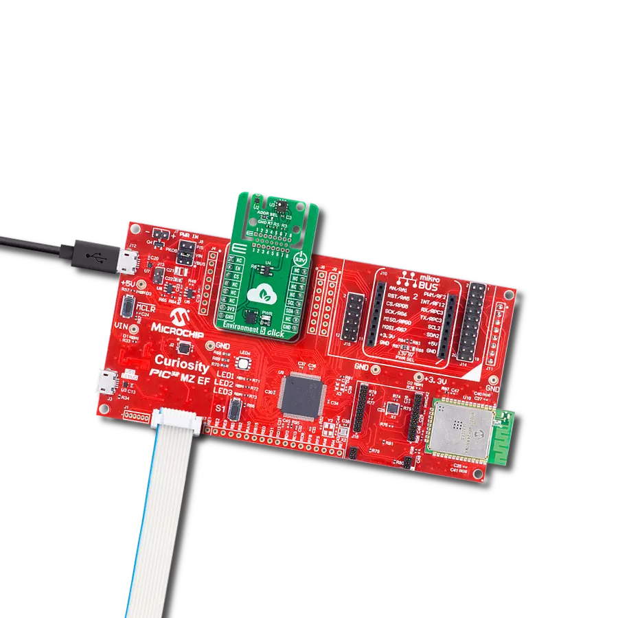
Start by selecting your development board and Click board™. Begin with the Clicker 2 for Kinetis as your development board.


Software Support
Library Description
Environment 5 Click demo application is developed using the NECTO Studio, ensuring compatibility with mikroSDK's open-source libraries and tools. Designed for plug-and-play implementation and testing, the demo is fully compatible with all development, starter, and mikromedia boards featuring a mikroBUS™ socket.
Example Description
This example demonstrates the use of the Environment 5 Click board, which provides temperature, humidity, and CO2 concentration measurements. The example initializes the device, reads sensor IDs, and continuously logs environmental data.
Key functions:
environment5_cfg_setup- This function initializes Click configuration structure to initial values.environment5_init- This function initializes all necessary pins and peripherals used for this Click board.environment5_default_cfg- This function executes a default configuration of Environment 5 Click board.environment5_sht_read_meas_hp- This function reads the temperature and humidity measurements with high precision from SHT40 device.environment5_stc_set_hum- This function sets the relative humidity compensation value on the STC31-C device.environment5_stc_read_meas- This function reads gas concentration and temperature data from the STC31-C device.
Application Init
Initializes the logger and configures the Environment 5 Click board. It also retrieves and logs the product and serial numbers of the onboard sensors.
Application Task
Continuously reads and logs temperature (degC) and humidity (%RH), and CO2 concentration (vol%) from sensors.
Open Source
Code example
The complete application code and a ready-to-use project are available through the NECTO Studio Package Manager for direct installation in the NECTO Studio. The application code can also be found on the MIKROE GitHub account.
/*!
 * @file main.c
 * @brief Environment 5 Click example
 *
 * # Description
 * This example demonstrates the use of the Environment 5 Click board, which provides
 * temperature, humidity, and CO2 concentration measurements. The example initializes
 * the device, reads sensor IDs, and continuously logs environmental data.
 *
 * The demo application is composed of two sections:
 *
 * ## Application Init
 * Initializes the logger and configures the Environment 5 Click board. It also retrieves
 * and logs the product and serial numbers of the onboard sensors.
 *
 * ## Application Task
 * Continuously reads and logs temperature (degC) and humidity (%RH), and CO2 concentration
 * (vol%) from sensors.
 *
 * @author Stefan Filipovic
 *
 */

#include "board.h"
#include "log.h"
#include "environment5.h"

static environment5_t environment5;
static log_t logger;

void application_init ( void )
{
    log_cfg_t log_cfg;  /**< Logger config object. */
    environment5_cfg_t environment5_cfg;  /**< Click config object. */

    /**
     * Logger initialization.
     * Default baud rate: 115200
     * Default log level: LOG_LEVEL_DEBUG
     * @note If USB_UART_RX and USB_UART_TX
     * are defined as HAL_PIN_NC, you will
     * need to define them manually for log to work.
     * See @b LOG_MAP_USB_UART macro definition for detailed explanation.
     */
    LOG_MAP_USB_UART( log_cfg );
    log_init( &logger, &log_cfg );
    log_info( &logger, " Application Init " );

    // Click initialization.
    environment5_cfg_setup( &environment5_cfg );
    ENVIRONMENT5_MAP_MIKROBUS( environment5_cfg, MIKROBUS_1 );
    if ( I2C_MASTER_ERROR == environment5_init( &environment5, &environment5_cfg ) )
    {
        log_error( &logger, " Communication init." );
        for ( ; ; );
    }

    if ( ENVIRONMENT5_ERROR == environment5_default_cfg ( &environment5 ) )
    {
        log_error( &logger, " Default configuration." );
        for ( ; ; );
    }

    uint32_t stc_prod_num = 0;
    uint32_t stc_serial_msb = 0;
    uint32_t stc_serial_lsb = 0;
    if ( ENVIRONMENT5_OK == environment5_stc_read_id ( &environment5, &stc_prod_num, &stc_serial_msb, &stc_serial_lsb ) )
    {
        log_printf ( &logger, " STC31-C Product number: 0x%.8LX\r\n", stc_prod_num );
        log_printf ( &logger, " STC31-C Serial number: 0x%.8LX%.8LX\r\n", stc_serial_msb, stc_serial_lsb );
    }

    uint32_t sht_serial = 0;
    if ( ENVIRONMENT5_OK == environment5_sht_read_serial ( &environment5, &sht_serial ) )
    {
        log_printf ( &logger, " SHT40 Serial number: 0x%.8LX\r\n", sht_serial );
    }

    log_info( &logger, " Application Task " );
}

void application_task ( void )
{
    float temperature = 0;
    float humidity = 0;
    float co2_concentration = 0;

    err_t error_flag = environment5_sht_read_meas_hp ( &environment5, &temperature, &humidity );
    if ( ENVIRONMENT5_OK == error_flag )
    {
        error_flag |= environment5_stc_set_temp ( &environment5, temperature );
        error_flag |= environment5_stc_set_hum ( &environment5, humidity );
        error_flag |= environment5_stc_read_meas ( &environment5, &co2_concentration, NULL );
    }

    if ( ENVIRONMENT5_OK == error_flag )
    {
        log_printf ( &logger, " Temperature: %.2f degC\r\n", temperature );
        log_printf ( &logger, " Humidity: %.2f %%RH\r\n", humidity );
        log_printf ( &logger, " CO2 in air [0-40]: %.2f vol%%\r\n\n", co2_concentration );
    }

    Delay_ms ( 500 );
}

int main ( void )
{
    /* Do not remove this line or clock might not be set correctly. */
    #ifdef PREINIT_SUPPORTED
    preinit();
    #endif

    application_init( );

    for ( ; ; )
    {
        application_task( );
    }

    return 0;
}

// ------------------------------------------------------------------------ END
Additional Support
Resources
Category:Environmental