Experience the future of smart agriculture with MIC1557 and PIC32MZ1024EFH064
Unearth growth secrets through capacitive moisture mastery!
Published Aug 24, 2023
Click board™
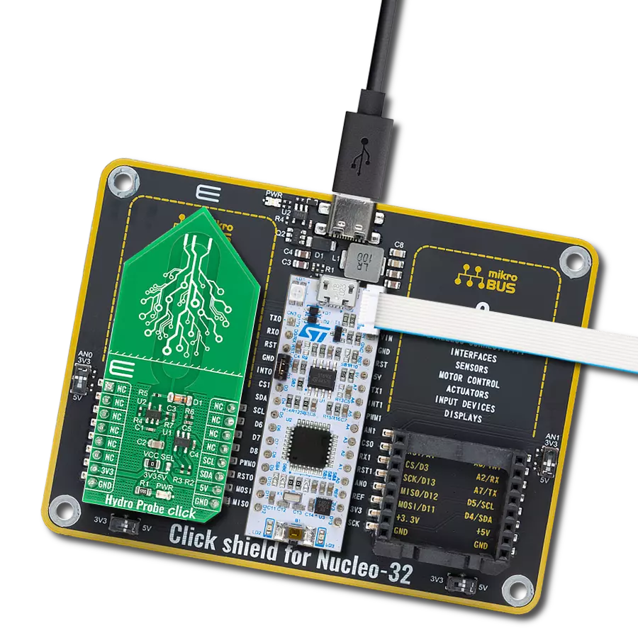
Hydro Probe Click
Dev. board
PIC32MZ clicker
Compiler
NECTO Studio
MCU
PIC32MZ1024EFH064
From sustainable gardening to precision farming, our capacitive soil moisture sensing solution offers unparalleled accuracy, helping you make informed decisions by monitoring volumetric water content in the soil
A
A
Hardware Overview
How does it work?
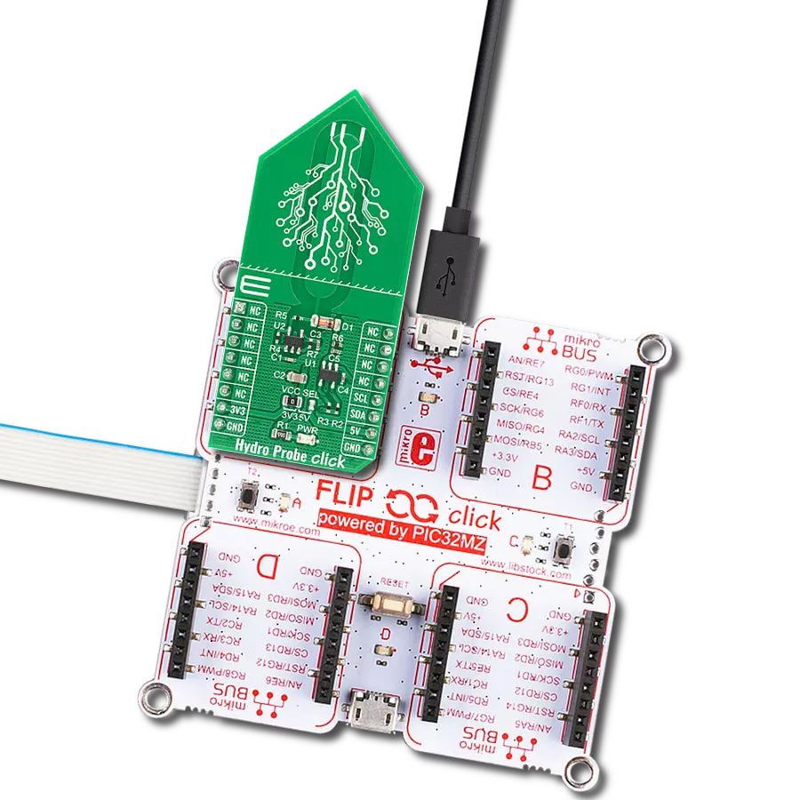
Hydro Probe Click uses the capacitive soil moisture sensor based on capacitive changes that are used to detect the volumetric water content of the soil. It based its operation on capacitive measurement, which has a great advantage over resistive measurement. Compared with resistive soil moisture sensors, capacitive sensors do not require direct exposure to the metal electrodes, which can significantly reduce the erosion of the electrodes. This Click board™ can only qualitatively test the humidity of the soil and can’t measure quantitatively. When the humidity of the soil rises, the output value decreases; conversely, when the humidity decreases, the output value becomes higher. It operates with a flexible power
supply voltage range, making it suitable for 3.3V and 5V MCUs. Hydro Probe Click functions as a capacitive soil moisture sensor using two main components, CMOS RC oscillator MIC1557 and 12-bit A/D converter MCP3221 with I2C serial interface. The oscillator frequency is set to 600kHz. From the oscillator, a signal goes to the soil moisture probe through a 10k resistor; these two elements act as a low-pass filter for the oscillator signal. The output analog signal from the capacitive probe goes through a diode to the MCP3221, A/D converter with 12-bit resolution, which converts that data and sends it to MCU. Communication to the MCP3221 is performed using a 2-wire I2C serial interface with available standard (100 kHz) or fast
(400 kHz) modes. To ensure you received the correct data, the Hydro Probe Click must be calibrated. The final output value is affected by probe insertion depth and how tight the soil packed around it is. It‘s recommended that the probe should not be placed on the depth which crosses the limit line on the Click board. This Click board™ can operate with either 3.3V or 5V logic voltage levels selected via the VCC SEL jumper. This way, both 3.3V and 5V capable MCUs can use the communication lines properly. Also, this Click board™ comes equipped with a library containing easy-to-use functions and an example code that can be used, as a reference, for further development.


Features overview
Development board
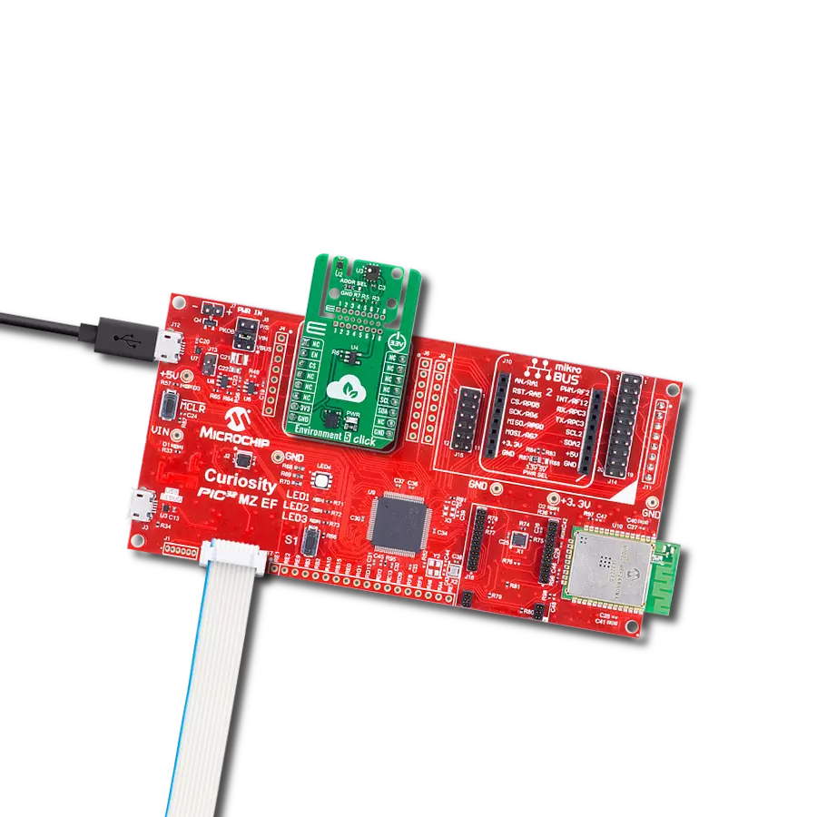
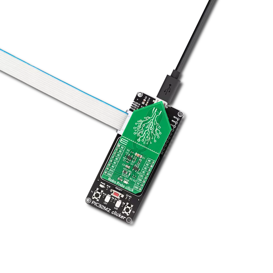
PIC32MZ Clicker is a compact starter development board that brings the flexibility of add-on Click boards™ to your favorite microcontroller, making it a perfect starter kit for implementing your ideas. It comes with an onboard 32-bit PIC32MZ microcontroller with FPU from Microchip, a USB connector, LED indicators, buttons, a mikroProg connector, and a header for interfacing with external electronics. Thanks to its compact design with clear and easy-recognizable silkscreen markings, it provides a fluid and immersive working experience, allowing access anywhere and under
any circumstances. Each part of the PIC32MZ Clicker development kit contains the components necessary for the most efficient operation of the same board. In addition to the possibility of choosing the PIC32MZ Clicker programming method, using USB HID mikroBootloader, or through an external mikroProg connector for PIC, dsPIC, or PIC32 programmer, the Clicker board also includes a clean and regulated power supply module for the development kit. The USB Micro-B connection can provide up to 500mA of current, which is more than enough to operate all onboard
and additional modules. All communication methods that mikroBUS™ itself supports are on this board, including the well-established mikroBUS™ socket, reset button, and several buttons and LED indicators. PIC32MZ Clicker is an integral part of the Mikroe ecosystem, allowing you to create a new application in minutes. Natively supported by Mikroe software tools, it covers many aspects of prototyping thanks to a considerable number of different Click boards™ (over a thousand boards), the number of which is growing every day.

Microcontroller Overview
MCU Card / MCU

Architecture
PIC32
MCU Memory (KB)
1024
Silicon Vendor
Microchip
Pin count
64
RAM (Bytes)
524288
You complete me!
Accessories
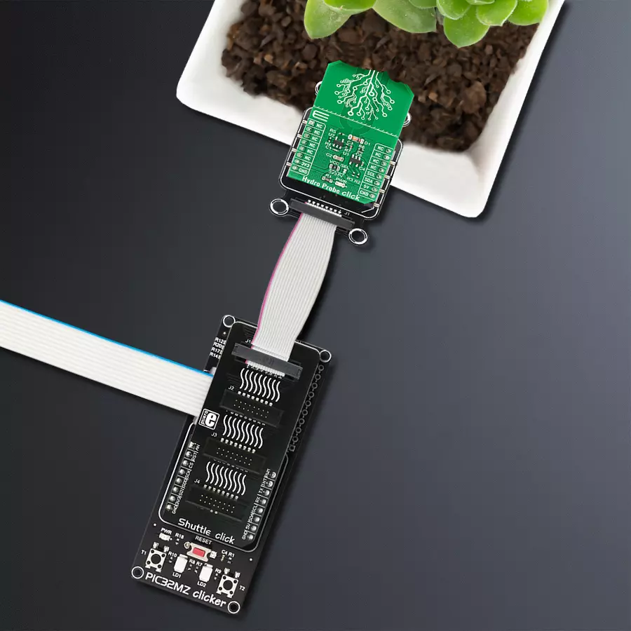
mikroBUS Shuttle Bundle is designed to significantly expand development systems by providing additional mikroBUS™ slots for integrating multiple Click boards™. It is based on the Shuttle click, which enables connection of mikroBUS Shuttle add-on boards via ICD BOX headers. The key feature of this board is its near-unlimited stacking capacity, allowing numerous mikroBUS™ connections while maintaining mirrored pin functionality across all ICD BOX headers. However, caution is advised with signal line length and power distribution, especially when using high-frequency communication protocols or power-hungry Click boards™. I2C and 1-Wire protocols are especially suitable due to built-in collision avoidance and address configuration options. This makes the Shuttle click an ideal solution for complex prototyping setups that require simultaneous use of various Click boards™, including sensors, communication modules, and control interfaces.

Used MCU Pins
mikroBUS™ mapper
Take a closer look
Click board™ Schematic

Step by step
Project assembly

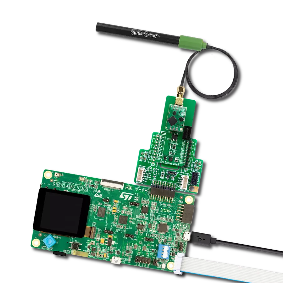
Start by selecting your development board and Click board™. Begin with the PIC32MZ clicker as your development board.


Software Support
Library Description
This library contains API for Hydro Probe Click driver.
Key functions:
hydroprobe_avg_val- Get average value functionhydroprobe_min_val- Get minimum value functionhydroprobe_rel_env_hum- Get Relative humidity of the environment function
Open Source
Code example
The complete application code and a ready-to-use project are available through the NECTO Studio Package Manager for direct installation in the NECTO Studio. The application code can also be found on the MIKROE GitHub account.
/*!
 * \file
 * \brief HydroProbe Click example
 *
 * # Description
 * This demo application measures moisture.
 *
 * The demo application is composed of two sections :
 *
 * ## Application Init
 * Initalizes I2C driver, prerforms calibration and makes an initial log.
 *
 * ## Application Task
 * This example shows the capabilities of the Hydro Probe Click by measuring
 * environment moisture content and displaying it in percent via USB UART.
 *
 * \author MikroE Team
 *
 */
// ------------------------------------------------------------------- INCLUDES

#include "board.h"
#include "log.h"
#include "hydroprobe.h"

// ------------------------------------------------------------------ VARIABLES

static hydroprobe_t hydroprobe;
static log_t logger;

static uint8_t humy_val = 0;
static uint16_t dry_val = 0;
static uint16_t wet_val = 0;

// ------------------------------------------------------- ADDITIONAL FUNCTIONS

void hydroprobe_calib ( )
{
    uint8_t cnt;

    log_printf( &logger, " Keep the Probe dry \r\n" );
    dry_val = hydroprobe_max_val( &hydroprobe );
    Delay_ms ( 1000 );
    Delay_ms ( 1000 );
    Delay_ms ( 1000 );
    Delay_ms ( 1000 );
    Delay_ms ( 1000 );
    log_printf( &logger, " Submerge the Probe in liquid \r\n" );
    for ( cnt = 5; cnt > 0; cnt-- )
    {
        log_printf( &logger, " %d \r\n ", ( uint16_t ) cnt );
        Delay_ms ( 1000 );
    }
    log_printf( &logger, " Keep the Probe submerged \r\n" );
    Delay_ms ( 100 );
    wet_val = hydroprobe_min_val( &hydroprobe );
    log_printf( &logger, "--------------------\r\n" );
    Delay_ms ( 1000 );
    Delay_ms ( 1000 );
    Delay_ms ( 1000 );
    Delay_ms ( 1000 );
    Delay_ms ( 1000 );
}

// ------------------------------------------------------ APPLICATION FUNCTIONS

void application_init ( void )
{
    log_cfg_t log_cfg;
    hydroprobe_cfg_t cfg;

    /**
     * Logger initialization.
     * Default baud rate: 115200
     * Default log level: LOG_LEVEL_DEBUG
     * @note If USB_UART_RX and USB_UART_TX
     * are defined as HAL_PIN_NC, you will
     * need to define them manually for log to work.
     * See @b LOG_MAP_USB_UART macro definition for detailed explanation.
     */
    LOG_MAP_USB_UART( log_cfg );
    log_init( &logger, &log_cfg );
    log_info( &logger, "---- Application Init ----" );

    //  Click initialization.

    hydroprobe_cfg_setup( &cfg );
    HYDROPROBE_MAP_MIKROBUS( cfg, MIKROBUS_1 );
    hydroprobe_init( &hydroprobe, &cfg );

    Delay_ms ( 100 );

    log_printf( &logger, "---------------------\r\n" );
    log_printf( &logger, "  Hydro Probe Click  \r\n" );
    log_printf( &logger, "---------------------\r\n" );
    hydroprobe_calib( );
    log_printf( &logger, "     Calibrated      \r\n" );
    log_printf( &logger, "---------------------\r\n" );
    Delay_ms ( 1000 );
    Delay_ms ( 1000 );
    Delay_ms ( 1000 );
}

void application_task ( void )
{
    humy_val = hydroprobe_rel_env_hum( &hydroprobe, dry_val, wet_val );
    log_printf( &logger, "Environment moisture content: %d %% \r\n ", ( uint16_t ) humy_val );
    log_printf( &logger, "------------------------------\r\n" );
    Delay_ms ( 1000 );
}

int main ( void )
{
    /* Do not remove this line or clock might not be set correctly. */
    #ifdef PREINIT_SUPPORTED
    preinit();
    #endif

    application_init( );

    for ( ; ; )
    {
        application_task( );
    }

    return 0;
}

// ------------------------------------------------------------------------ END
Additional Support
Resources
Category:Environmental