Quickly identify and troubleshoot issues on the mikroBUS™ lines with STM32F446RE
Real-time mikroBUS™ pin monitoring solution featuring a 2x6 LED array and SI2310 MOSFETs

Published Feb 05, 2025
Click board™
Tester 2 Click
Dev. board
Nucleo 64 with STM32F446RE MCU
Compiler
NECTO Studio
MCU
STM32F446RE
Track mikroBUS™ pin logic levels in real time with visual feedback, perfect for debugging and troubleshooting embedded systems
A
A
Hardware Overview
How does it work?
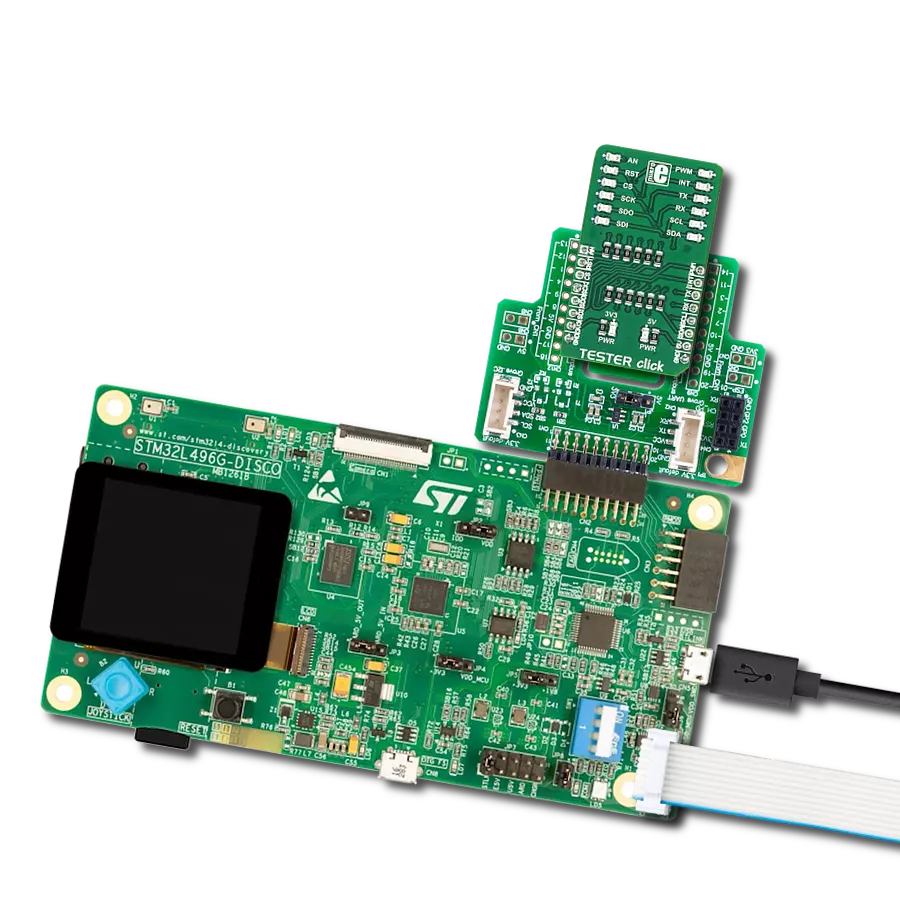
Tester 2 Click is a diagnostic Click board™ designed to provide immediate and reliable visual feedback on the logic levels of mikroBUS™ pins. It features a 2x6 array of orange LEDs, each connected to a specific mikroBUS™ pin, allowing developers to instantly determine whether the logic state on a pin is HIGH or LOW. For easy identification, each LED is clearly labeled with the name of the corresponding pin, such as PWM or AN. Additionally, the board includes two LEDs dedicated to monitoring the mikroBUS™ power rails, signaling the presence of +3.3V and +5V voltages. This functionality eliminates the need for additional diagnostic tools or complex measurement setups, saving developers valuable time and effort during debugging and troubleshooting. Using Tester 2 Click is straightforward. Once the board is inserted into the mikroBUS™ socket, it becomes fully operational without requiring additional configuration or setup. The power indication LEDs immediately signal the
presence of voltage on the mikroBUS™ power rails, while the rest of the LED array lights up based on the logic states of their respective pins. The simplicity of the design, which uses LEDs and SI2310 N-channel MOSFETs for controlling their operation, ensures reliability and ease of use, making it an indispensable tool for developers working with mikroBUS™ systems. The board is built to be fully compatible with the standardized mikroBUS™ connector, a key feature of MIKROE development systems. This connector ensures that all commonly used interfaces, including SPI, I2C, UART, PWM, analog input (AN), and various GPIO pins such as CS, INT, and RST, are consistently mapped across all platforms equipped with mikroBUS™ sockets. It also incorporates two power supply rails, +3.3V, and +5V, allowing compatibility between different systems and a wide range of Click boards™. This standardization means that Tester 2 Click can be used across various platforms without requiring hardware
modifications, ensuring flexibility and ease of integration for developers. A notable addition to this board is a switch that activates the ClickID feature, allowing the signal from ClickID to be used on the CS pin instead of the standard SPI Chip Select functionality. Additionally, the board includes LP CUT traces on its backside, which are designed to support low-power operation. By severing these traces, the power supply to the LEDs and the ClickID section is disconnected, drastically reducing power consumption and enabling efficient operation, especially in applications where energy efficiency is critical. This Click board™ can operate with either 3.3V or 5V logic voltage levels selected via the VCC SEL jumper. This way, both 3.3V and 5V capable MCUs can use the communication lines properly. Also, this Click board™ comes equipped with a library containing easy-to-use functions and an example code that can be used as a reference for further development.

Features overview
Development board
Nucleo-64 with STM32F446RE MCU offers a cost-effective and adaptable platform for developers to explore new ideas and prototype their designs. This board harnesses the versatility of the STM32 microcontroller, enabling users to select the optimal balance of performance and power consumption for their projects. It accommodates the STM32 microcontroller in the LQFP64 package and includes essential components such as a user LED, which doubles as an ARDUINO® signal, alongside user and reset push-buttons, and a 32.768kHz crystal oscillator for precise timing operations. Designed with expansion and flexibility in mind, the Nucleo-64 board features an ARDUINO® Uno V3 expansion connector and ST morpho extension pin
headers, granting complete access to the STM32's I/Os for comprehensive project integration. Power supply options are adaptable, supporting ST-LINK USB VBUS or external power sources, ensuring adaptability in various development environments. The board also has an on-board ST-LINK debugger/programmer with USB re-enumeration capability, simplifying the programming and debugging process. Moreover, the board is designed to simplify advanced development with its external SMPS for efficient Vcore logic supply, support for USB Device full speed or USB SNK/UFP full speed, and built-in cryptographic features, enhancing both the power efficiency and security of projects. Additional connectivity is
provided through dedicated connectors for external SMPS experimentation, a USB connector for the ST-LINK, and a MIPI® debug connector, expanding the possibilities for hardware interfacing and experimentation. Developers will find extensive support through comprehensive free software libraries and examples, courtesy of the STM32Cube MCU Package. This, combined with compatibility with a wide array of Integrated Development Environments (IDEs), including IAR Embedded Workbench®, MDK-ARM, and STM32CubeIDE, ensures a smooth and efficient development experience, allowing users to fully leverage the capabilities of the Nucleo-64 board in their projects.

Microcontroller Overview
MCU Card / MCU

Architecture
ARM Cortex-M4
MCU Memory (KB)
512
Silicon Vendor
STMicroelectronics
Pin count
64
RAM (Bytes)
131072
You complete me!
Accessories
Click Shield for Nucleo-64 comes equipped with two proprietary mikroBUS™ sockets, allowing all the Click board™ devices to be interfaced with the STM32 Nucleo-64 board with no effort. This way, Mikroe allows its users to add any functionality from our ever-growing range of Click boards™, such as WiFi, GSM, GPS, Bluetooth, ZigBee, environmental sensors, LEDs, speech recognition, motor control, movement sensors, and many more. More than 1537 Click boards™, which can be stacked and integrated, are at your disposal. The STM32 Nucleo-64 boards are based on the microcontrollers in 64-pin packages, a 32-bit MCU with an ARM Cortex M4 processor operating at 84MHz, 512Kb Flash, and 96KB SRAM, divided into two regions where the top section represents the ST-Link/V2 debugger and programmer while the bottom section of the board is an actual development board. These boards are controlled and powered conveniently through a USB connection to program and efficiently debug the Nucleo-64 board out of the box, with an additional USB cable connected to the USB mini port on the board. Most of the STM32 microcontroller pins are brought to the IO pins on the left and right edge of the board, which are then connected to two existing mikroBUS™ sockets. This Click Shield also has several switches that perform functions such as selecting the logic levels of analog signals on mikroBUS™ sockets and selecting logic voltage levels of the mikroBUS™ sockets themselves. Besides, the user is offered the possibility of using any Click board™ with the help of existing bidirectional level-shifting voltage translators, regardless of whether the Click board™ operates at a 3.3V or 5V logic voltage level. Once you connect the STM32 Nucleo-64 board with our Click Shield for Nucleo-64, you can access hundreds of Click boards™, working with 3.3V or 5V logic voltage levels.

Used MCU Pins
mikroBUS™ mapper
Take a closer look
Click board™ Schematic

Step by step
Project assembly
Start by selecting your development board and Click board™. Begin with the Nucleo 64 with STM32F446RE MCU as your development board.


Software Support
Library Description
Tester 2 Click demo application is developed using the NECTO Studio, ensuring compatibility with mikroSDK's open-source libraries and tools. Designed for plug-and-play implementation and testing, the demo is fully compatible with all development, starter, and mikromedia boards featuring a mikroBUS™ socket.
Example Description
This example demonstrates the use of Tester 2 Click board by controlling all LEDs on the Click board together and in sequential pin toggling with different delays.
Key functions:
tester2_cfg_setup- Config Object Initialization function.tester2_init- Initialization function.tester2_toggle_all- This function toggles all mikroBUS pins together a desired number of times with the selected delay between each toggle.tester2_toggle_seq- This function toggles all mikroBUS pins one by one with the selected delay between each toggle.
Application Init
Initializes the driver and logger.
Application Task
Toggles all pins together 5 times with a 500ms delay between each toggle, then toggles each pin sequentially with a 300ms delay between toggling each pin.
Open Source
Code example
The complete application code and a ready-to-use project are available through the NECTO Studio Package Manager for direct installation in the NECTO Studio. The application code can also be found on the MIKROE GitHub account.
/*!
 * @file main.c
 * @brief Tester 2 Click Example.
 *
 * # Description
 * This example demonstrates the use of Tester 2 Click board by controlling all
 * LEDs on the Click board together and in sequential pin toggling with different delays.
 *
 * The demo application is composed of two sections :
 *
 * ## Application Init
 * Initializes the driver and logger.
 *
 * ## Application Task
 * Toggles all pins together 5 times with a 500ms delay between each toggle, then toggles
 * each pin sequentially with a 300ms delay between toggling each pin.
 *
 * @author Stefan Filipovic
 *
 */

#include "board.h"
#include "log.h"
#include "tester2.h"

static tester2_t tester2;   /**< Tester 2 Click driver object. */
static log_t logger;    /**< Logger object. */

void application_init ( void )
{
    log_cfg_t log_cfg;  /**< Logger config object. */
    tester2_cfg_t tester2_cfg;  /**< Click config object. */

    /**
     * Logger initialization.
     * Default baud rate: 115200
     * Default log level: LOG_LEVEL_DEBUG
     * @note If USB_UART_RX and USB_UART_TX
     * are defined as HAL_PIN_NC, you will
     * need to define them manually for log to work.
     * See @b LOG_MAP_USB_UART macro definition for detailed explanation.
     */
    LOG_MAP_USB_UART( log_cfg );
    log_init( &logger, &log_cfg );
    log_info( &logger, " Application Init " );

    // Click initialization.
    tester2_cfg_setup( &tester2_cfg );
    TESTER2_MAP_MIKROBUS( tester2_cfg, MIKROBUS_1 );
    if ( DIGITAL_OUT_UNSUPPORTED_PIN == tester2_init( &tester2, &tester2_cfg ) )
    {
        log_error( &logger, " Communication init." );
        for ( ; ; );
    }

    log_info( &logger, " Application Task " );
}

void application_task ( void )
{
    log_printf( &logger, " Toggling all pins together 5 times with 500ms delay\r\n\n" );
    tester2_toggle_all ( &tester2, 5, 500 );

    log_printf( &logger, " Toggling all pins sequentially with 300ms delay\r\n\n" );
    tester2_toggle_seq ( &tester2, 300 );
}

int main ( void )
{
    /* Do not remove this line or clock might not be set correctly. */
    #ifdef PREINIT_SUPPORTED
    preinit();
    #endif

    application_init( );

    for ( ; ; )
    {
        application_task( );
    }

    return 0;
}

// ------------------------------------------------------------------------ END
Additional Support
Resources
Category:Proto