Reduce noise pollution with actionable data and insights using MCP4921 and PIC32MZ2048EFM064
Respond promptly to noise-related issues
Published Jul 22, 2025
Click board™
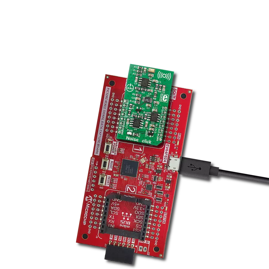
Noise Click
Dev. board
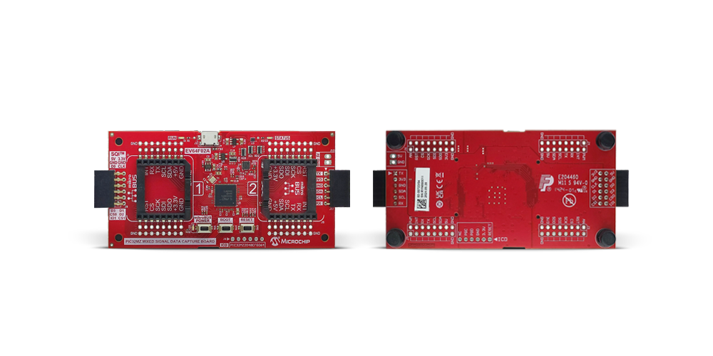
PIC32MZ MXS Data Capture Board
Compiler
NECTO Studio
MCU
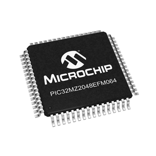
PIC32MZ2048EFM064
Our noise detection solution is engineered to identify and mitigate disruptive noise, fostering quieter and more peaceful environments
A
A
Hardware Overview
How does it work?
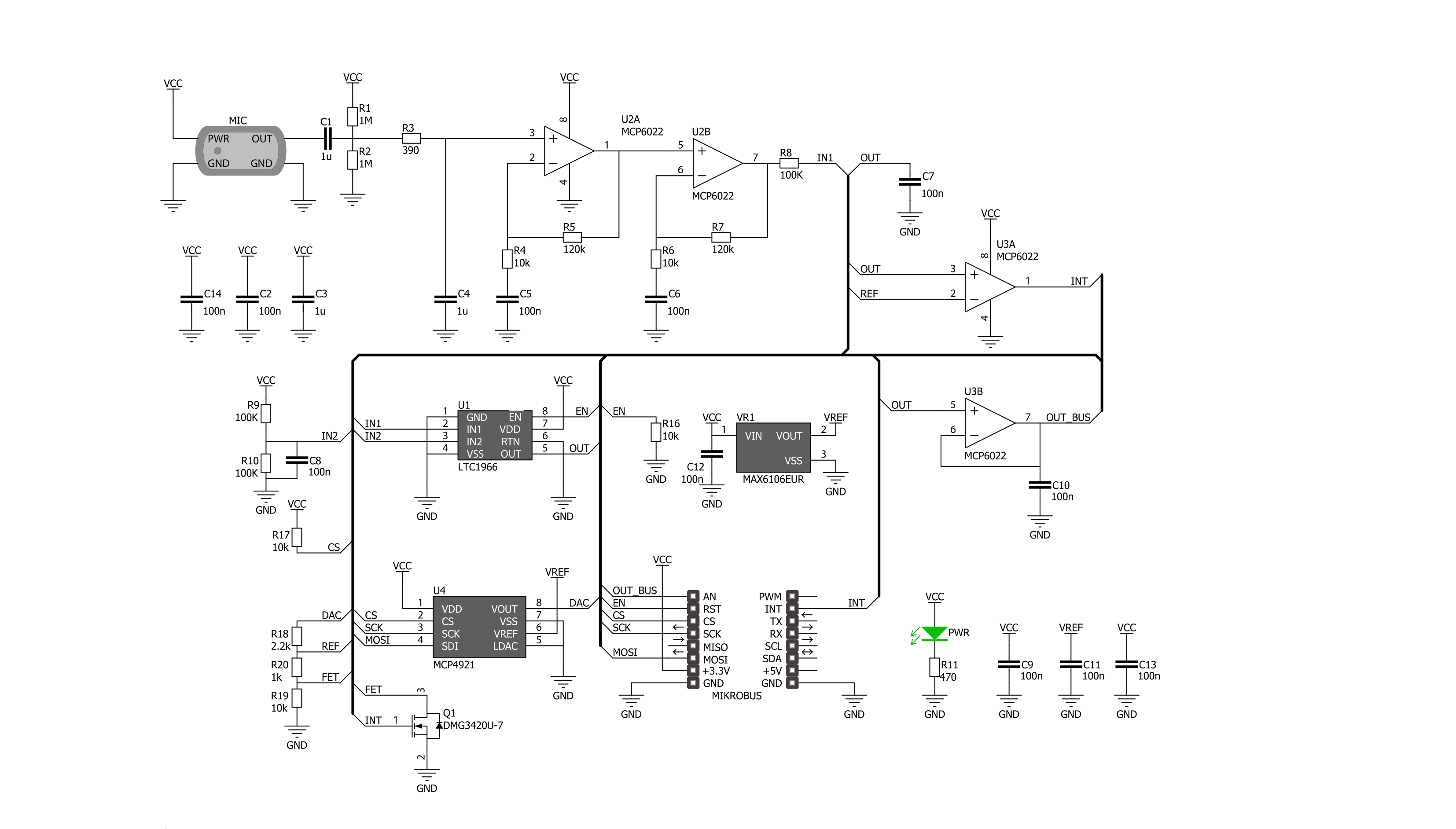
Noise Click is based on the MCP4921, a 12-bit DAC with an SPI interface from Microchip. This single-channel DAC has a rail-to-rail output, a fast-setting time, and 450KHz of multiplier mode. The MCP4921 on the Noise Click sets the threshold in 12-bit resolution steps from 0 up to 4096. The noise from the environment this Click board™ receives through the MM034202-11, an analog MEMS microphone from DB Unlimited. It has omnidirectional directivity, a sensitivity of around -42dB, a signal-to-noise ratio of 59dB, and works in a frequency range from 100 up to 10000Hz. This Click board™ also includes two MCP6022s, a rail-to-rail input/output 10MHz Op Amps from Microchip. The operational amplifiers feature wide bandwidth up to 10MHz, low noise, low input offset voltage, and low distortion. The first MCP6022
processes the microphone signal. Then, the amplified voltages pass through the LTC1966, a precision micropower ∆∑ RMS-to-DC converter from Analog Devices. This converter has constant bandwidth independent of the input voltage, flexible rail-to-rail inputs, and outputs and is more accurate than conventional log antilog similar RMS-to-DC converters. After processing with the LTC1966, the signal then goes into the second operational amplifier, which functions as a voltage comparator, from which the interrupt signal originates. To avoid triggering the interrupt hundreds of times per second as ambient noise oscillates near the threshold, a hysteresis circuit is also employed. For that purpose, the Noise Click comes with the MAX6106, a low-cost, micropower, low-dropout, high-output-current voltage
reference of 2.048V from Analog Devices. The Noise Click uses an SPI serial interface to communicate with the host MCU over the mikroBUS™ socket. The LTC1966 RMS-to-DC converter can be turned off with the HIGH logic state on the EN pin of the mikroBUS™ socket. No matter the logic state on the enable pin, the voltage levels can still be monitored over the AN pin. When the ambient noise reaches the set threshold, the interrupt INT pin is pulled HIGH. This Click board™ can be operated only with a 3.3V logic voltage level. The board must perform appropriate logic voltage level conversion before using MCUs with different logic levels. Also, it comes equipped with a library containing functions and an example code that can be used as a reference for further development.


Features overview
Development board
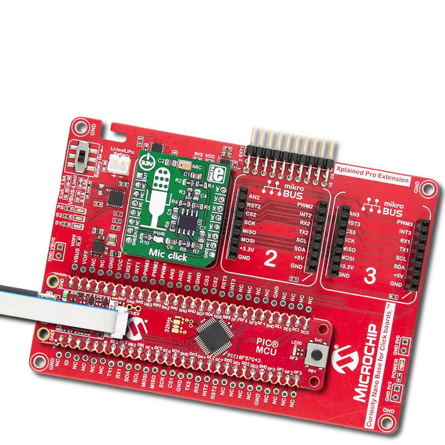
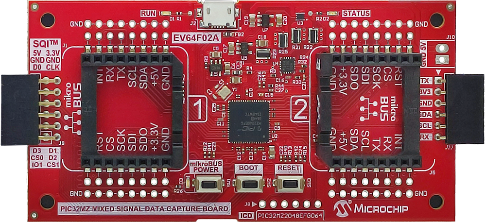
The PIC32MZ MXS Data Capture Board is a development platform designed to bridge mixed-signal demo boards - such as ADCs, DACs, digital potentiometers, and power monitors - with their respective graphical user interfaces. It features two mikroBUS™ sockets, each connected to dedicated peripheral modules within the powerful PIC32MZ microcontroller (PIC32MZ2048EFM064), enabling communication over SPI, I2C, and UART interfaces. Additionally, the board supports SQI™ communication through a dedicated 2x6 pin header, offering expanded connectivity for serial memory devices and high-speed data acquisition. The second mikroBUS™ socket shares its UART and I2C lines with a PicKit Serial 1x6 header, providing backward compatibility with legacy tools like the PicKit Serial Analyzer and the MCP2221A Breakout
Module. For advanced power management, the board integrates a PAC1944 power monitoring IC capable of measuring voltage and current across all four mikroBUS™ power rails (5V and 3.3V). Each 3.3V rail is powered by an independent 150mA low-dropout regulator, while the microcontroller receives power through a separate 300mA LDO, ensuring stable and isolated power domains. Users can toggle the mikroBUS™ power supply via a dedicated button or software control, with monitoring and override capability provided by the MCU. The microcontroller comes preprogrammed with a factory bootloader that enables firmware updates via USB using the Microchip Bootloader Utility, which works in conjunction with the MCHP USB Bridge Service to deliver appropriate firmware packages depending on the connected demo
board. A recovery bootloader HEX file (EV64F02A\_Bootloader.hex) is also provided for restoring the default firmware using an external PicKit or ICD programmer in case the board is repurposed for custom applications. To support device communication and scripting, a generic SPI and I2C Data Capture GUI is included, allowing users to interface with any compatible device connected to the mikroBUS™ sockets, toggle remaining I/O pins, and initiate firmware updates directly from the GUI or through a web browser. Designed for versatility and ease of integration, the PIC32MZ Mixed Signal Data Capture Board offers a robust solution for evaluating and communicating with a wide range of mixed-signal devices.
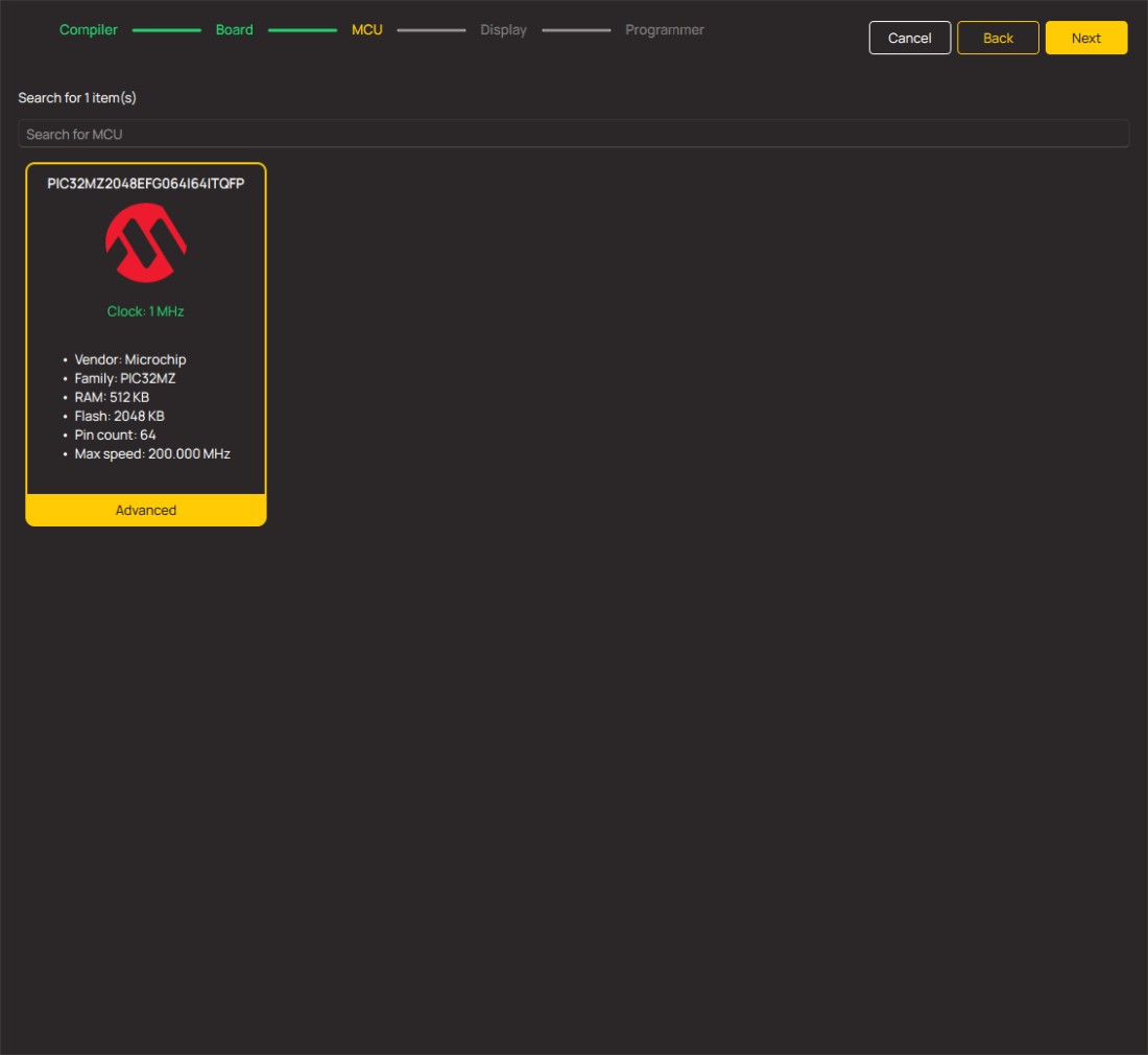
Microcontroller Overview
MCU Card / MCU
Architecture
PIC32
MCU Memory (KB)
2048
Silicon Vendor
Microchip
Pin count
64
RAM (Bytes)
524288
Used MCU Pins
mikroBUS™ mapper
Take a closer look
Click board™ Schematic
Step by step
Project assembly
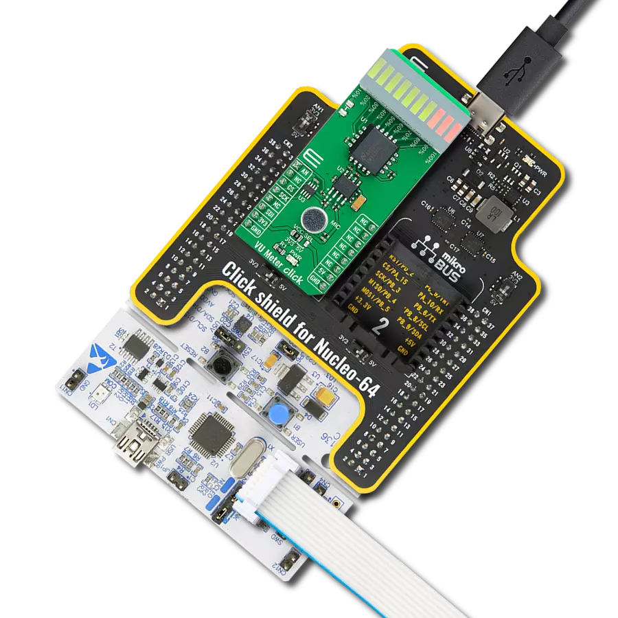
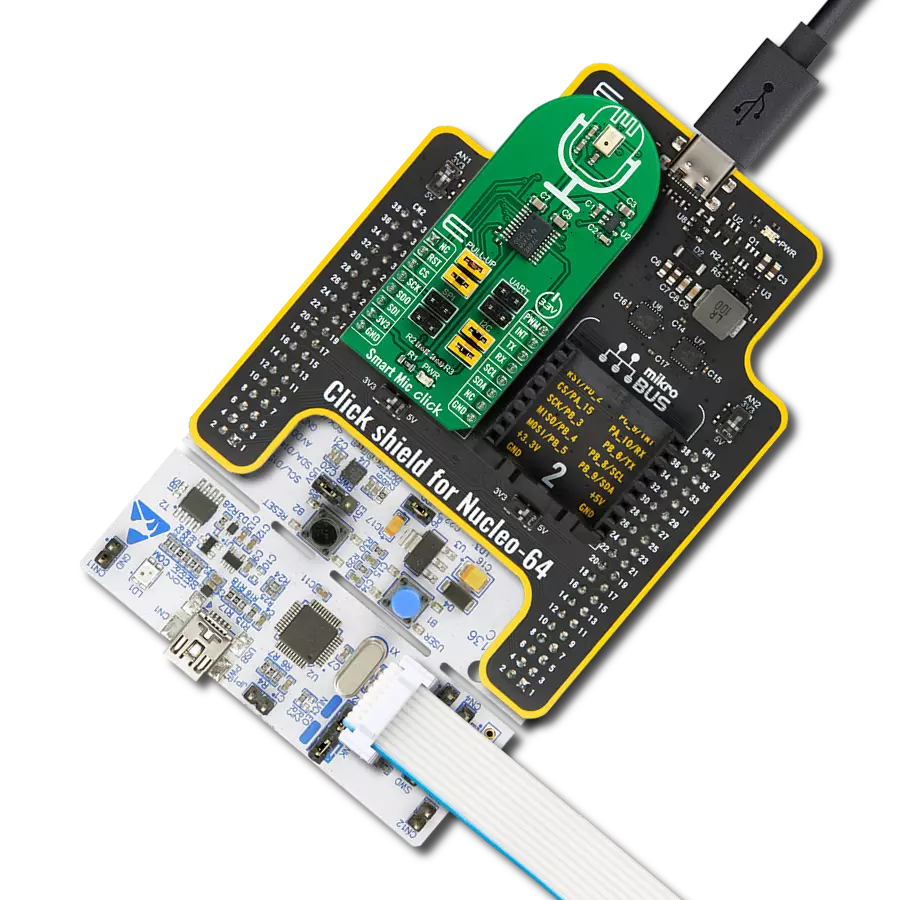
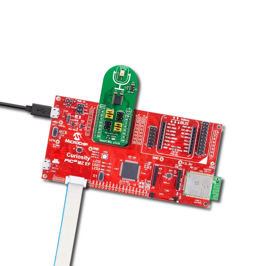
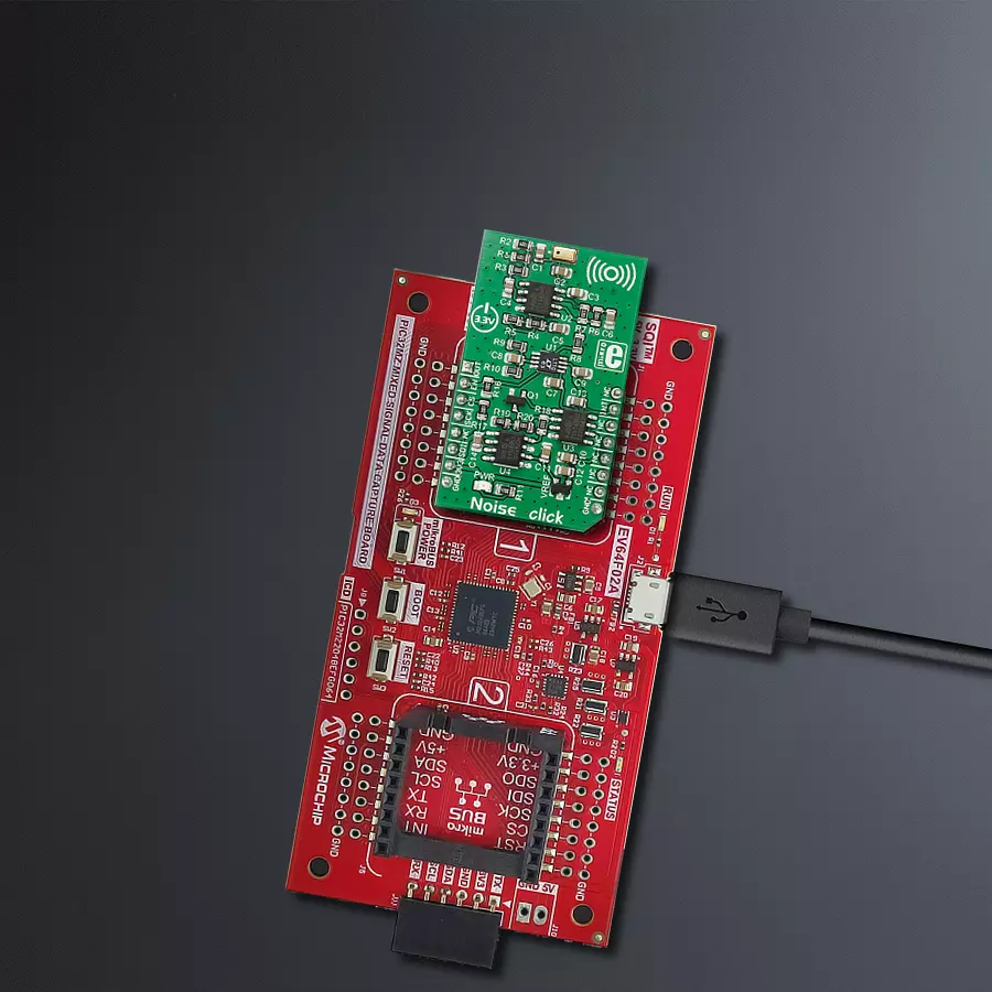
Start by selecting your development board and Click board™. Begin with the PIC32MZ MXS Data Capture Board as your development board.


Software Support
Library Description
This library contains API for Noise Click driver.
Key functions:
noise_set_cmd_reg- This function sets command registernoise_set_state- This function switches click ON or OFFnoise_read_an_pin_voltage- This function reads results of AD conversion of the AN pin and converts them to proportional voltage level
Open Source
Code example
The complete application code and a ready-to-use project are available through the NECTO Studio Package Manager for direct installation in the NECTO Studio. The application code can also be found on the MIKROE GitHub account.
/*!
 * \file
 * \brief Noise Click example
 *
 * # Description
 * This example performs an ambient noise monitoring using the Noise Click board.
 *
 * The demo application is composed of two sections :
 *
 * ## Application Init
 * Device initialization.
 *
 * ## Application Task
 * Reads the voltage from AN pin which presents the noise level and displays it
 * on the USB UART every 5ms. If the noise is above predefined threshold
 * (25 percents of max noise, i.e. about 0.4V) an alarm message is being shown.
 *
 * @note
 * We recommend using the SerialPlot tool for data visualizing.
 *
 * \author MikroE Team
 *
 */
#include "board.h"
#include "log.h"
#include "noise.h"

static noise_t noise;
static log_t logger;

void application_init ( void )
{
    log_cfg_t log_cfg;
    noise_cfg_t cfg;

    /**
     * Logger initialization.
     * Default baud rate: 115200
     * Default log level: LOG_LEVEL_DEBUG
     * @note If USB_UART_RX and USB_UART_TX
     * are defined as HAL_PIN_NC, you will
     * need to define them manually for log to work.
     * See @b LOG_MAP_USB_UART macro definition for detailed explanation.
     */
    LOG_MAP_USB_UART( log_cfg );
    log_init( &logger, &log_cfg );
    log_info( &logger, "---- Application Init ----" );

    //  Click initialization.
    noise_cfg_setup( &cfg );
    NOISE_MAP_MIKROBUS( cfg, MIKROBUS_1 );
    noise_init( &noise, &cfg );

    noise_default_cfg( &noise );
}

void application_task ( void )
{
    float voltage = 0;
    if ( NOISE_OK == noise_read_an_pin_voltage ( &noise, &voltage ) )
    {
        log_printf( &logger, "%.3f\r\n", voltage );
    }
    if ( noise_check_int_pin( &noise ) )
    {
        log_printf( &logger, " Sound overlimit detected!\r\n" );
    }
    Delay_ms ( 5 );
}

int main ( void )
{
    /* Do not remove this line or clock might not be set correctly. */
    #ifdef PREINIT_SUPPORTED
    preinit();
    #endif

    application_init( );

    for ( ; ; )
    {
        application_task( );
    }

    return 0;
}


// ------------------------------------------------------------------------ END
Additional Support
Resources
Category:Microphone