Achieve control tailored to your exact requirements with PCA9685 servo driver combined with STM32F302VC
Your control, your way: The PWM servo driver that adapts to any task
Published Jul 22, 2025
Click board™
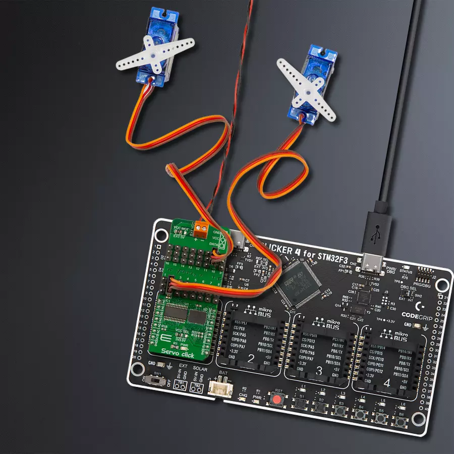
Servo Click
Dev. board
CLICKER 4 for STM32F302VCT6
Compiler
NECTO Studio
MCU
STM32F302VC
Our PWM servo driver offers the best of both worlds – sink 25mA for robust control and source up to 10mA for delicate, precision movements, ensuring your applications meet every demand
A
A
Hardware Overview
How does it work?
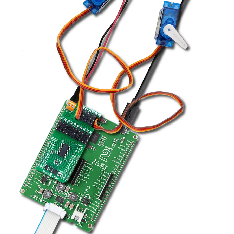
Servo Click is based on the PCA9685, an integrated 12-bit 16-channel PWM driver that can be configured to either sink 25mA per channel or drive each channel sourcing up to 10mA from NXP. Each channel's duty cycle is independently set from 0% to 100%. Offering 16 independent channels, each with its own PWM duty cycle and current sensing ability, this Click board™ represents a powerful servo controller, especially useful when many servos need to be controlled easily. The control PWM signal's frequency can be programmed from 24Hz to 1526Hz. The servo can be connected to any of the sixteen headers on this Click board™. The output signal frequency is determined by the Prescaler value, which is written to the appropriate register. The output channels can be set in the open-drain or push-pull configuration. In the first case, they can sink up to 25mA from up to 5V power supply, while in the second case, they can both drive with up to 10mA
or sink up to 25mA. This Click board™ also has an accurate 16-bit A/D converter, the LTC2497 from Analog Devices, used to sample the voltage drop across the shunt resistor on each of the 16 channels, giving feedback on the servo current consumption. The ADC uses an accurate reference of 2.048V provided by an onboard reference voltage regulator MAX6106 from Analog Devices. An extremely low noise of this ADC coupled with a low reference voltage allows small voltage drops across the shunt resistor to be accurately converted. Servo Click communicates with MCU using the standard I2C 2-Wire interface with a frequency up to 100kHz in the Standard, 400 kHz in the Fast, and 1MHz in the Fast-Plus mode. There are two more SMD jumpers, labeled as the PWM and ADC, located at the bottom of the Click board™ that allow the selection of the I2C address for each of the two onboard ICs. It also has an external connector that can provide more power
for servos with heavier loads. That's why the SMD jumper labeled VCC MOT should be at the EXT position. An external PSU that can provide more current can be used in this case. The PCA9685 also offers an Output Enable pin, routed to the mikroBUS™ CS pin, labeled as the OE. A LOW logic level on this pin will set all the outputs to the predefined logic state, turning the PWM generators OFF. Depending on the servo model, this may either leave the servo in the fixed position or turn it down completely. This Click board™ can operate with either 3.3V or 5V logic voltage levels selected via the VCC SEL jumper. This way, both 3.3V and 5V capable MCUs can use the communication lines properly. Also, this Click board™ comes equipped with a library containing easy-to-use functions and an example code that can be used as a reference for further development.

Features overview
Development board
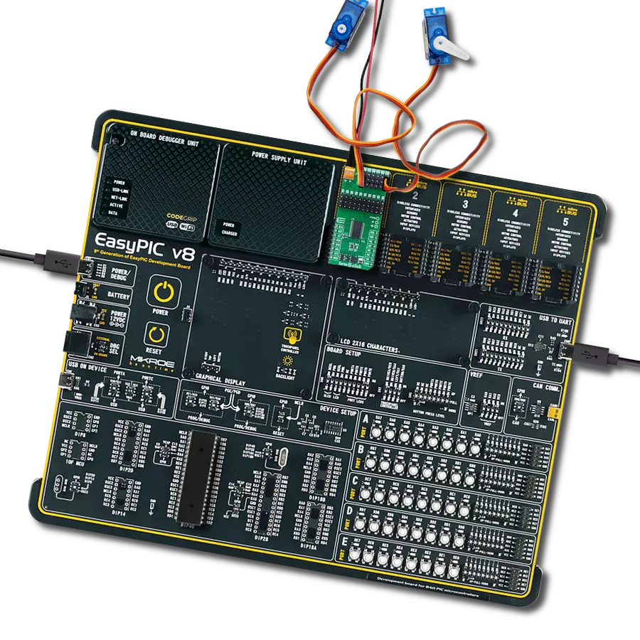
Clicker 4 for STM32F3 is a compact development board designed as a complete solution, you can use it to quickly build your own gadgets with unique functionalities. Featuring a STM32F302VCT6, four mikroBUS™ sockets for Click boards™ connectivity, power managment, and more, it represents a perfect solution for the rapid development of many different types of applications. At its core, there is a STM32F302VCT6 MCU, a powerful microcontroller by STMicroelectronics, based on the high-
performance Arm® Cortex®-M4 32-bit processor core operating at up to 168 MHz frequency. It provides sufficient processing power for the most demanding tasks, allowing Clicker 4 to adapt to any specific application requirements. Besides two 1x20 pin headers, four improved mikroBUS™ sockets represent the most distinctive connectivity feature, allowing access to a huge base of Click boards™, growing on a daily basis. Each section of Clicker 4 is clearly marked, offering an intuitive and clean interface. This makes working with the development
board much simpler and thus, faster. The usability of Clicker 4 doesn’t end with its ability to accelerate the prototyping and application development stages: it is designed as a complete solution which can be implemented directly into any project, with no additional hardware modifications required. Four mounting holes [4.2mm/0.165”] at all four corners allow simple installation by using mounting screws. For most applications, a nice stylish casing is all that is needed to turn the Clicker 4 development board into a fully functional, custom design.

Microcontroller Overview
MCU Card / MCU

Architecture
ARM Cortex-M4
MCU Memory (KB)
256
Silicon Vendor
STMicroelectronics
Pin count
100
RAM (Bytes)
40960
Used MCU Pins
mikroBUS™ mapper
Take a closer look
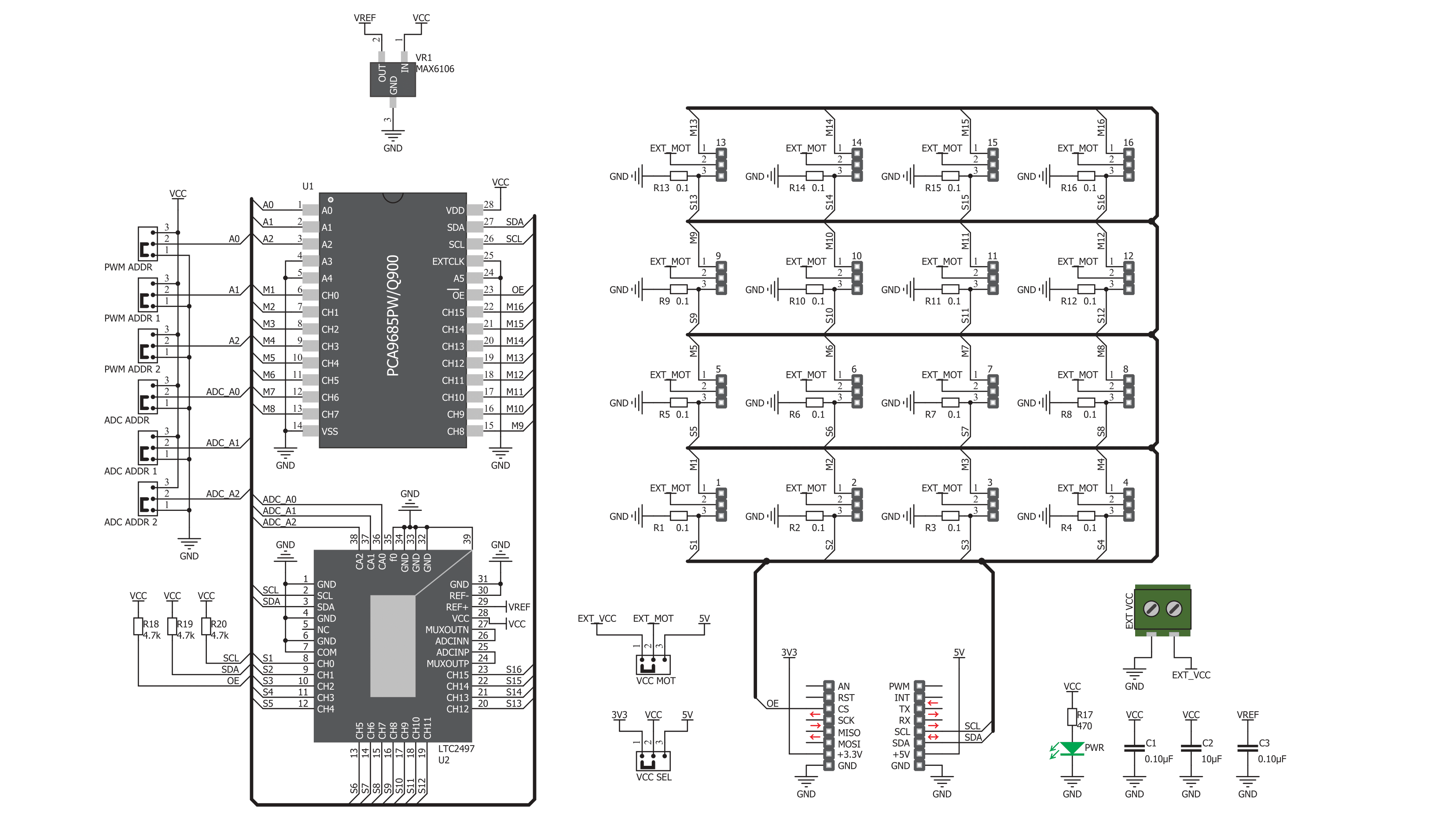
Click board™ Schematic
Step by step
Project assembly

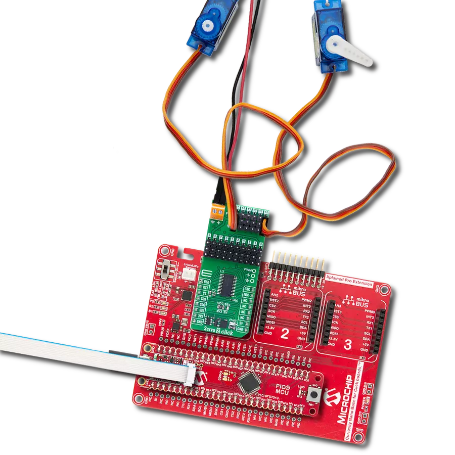
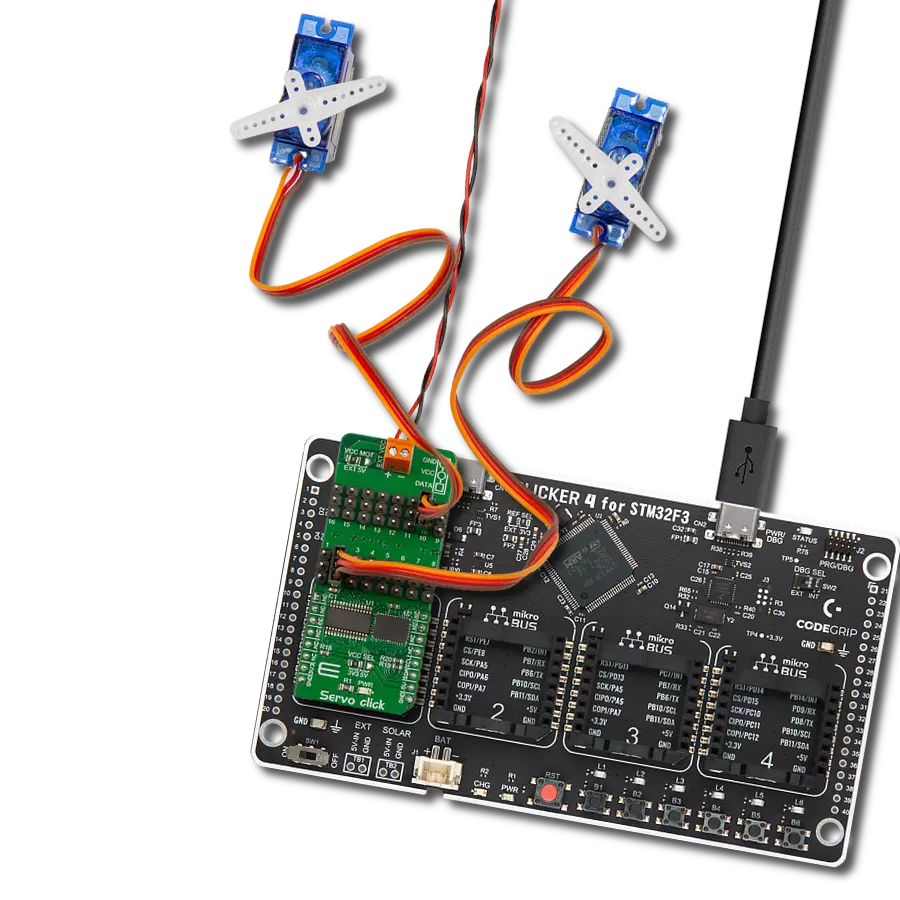
Start by selecting your development board and Click board™. Begin with the CLICKER 4 for STM32F302VCT6 as your development board.


Software Support
Library Description
This library contains API for Servo Click driver.
Key functions:
servo_set_vref- This function settings Vref of Servo Clickservo_set_position- This function sets positionsetvo_get_current- This function reads the current value of Servo Click witch motor spends
Open Source
Code example
The complete application code and a ready-to-use project are available through the NECTO Studio Package Manager for direct installation in the NECTO Studio. The application code can also be found on the MIKROE GitHub account.
/*!
 * \file
 * \brief Servo Click example
 *
 * # Description
 * This app shows how the servo motor can be controled by the Click board.
 *
 * The demo application is composed of two sections :
 *
 * ## Application Init
 * Initializes device.
 *
 * ## Application Task
 * The servo motor at CH1 rotate in clockwise and counter clockwise directions.
 *
 * \author MikroE Team
 *
 */
// ------------------------------------------------------------------- INCLUDES

#include "board.h"
#include "log.h"
#include "servo.h"

// ------------------------------------------------------------------ VARIABLES

static servo_t servo;
static log_t logger;
static int16_t cnt;

// ------------------------------------------------------ APPLICATION FUNCTIONS

void application_init ( void )
{
    log_cfg_t log_cfg;
    servo_cfg_t cfg;

    /**
     * Logger initialization.
     * Default baud rate: 115200
     * Default log level: LOG_LEVEL_DEBUG
     * @note If USB_UART_RX and USB_UART_TX
     * are defined as HAL_PIN_NC, you will
     * need to define them manually for log to work.
     * See @b LOG_MAP_USB_UART macro definition for detailed explanation.
     */
    LOG_MAP_USB_UART( log_cfg );
    log_init( &logger, &log_cfg );
    log_info( &logger, "---- Application Init ----" );

    //  Click initialization.

    servo_cfg_setup( &cfg );
    SERVO_MAP_MIKROBUS( cfg, MIKROBUS_1 );
    servo_init( &servo, &cfg );

    servo_default_cfg( &servo );
}

void application_task ( void )
{
    log_printf( &logger, "<<< Counter clockwise >>>\r\n" );
    Delay_1sec( );

    for ( cnt = servo.min_pos; cnt <= servo.max_pos; cnt++ )
    {
        servo_set_position( &servo, SERVO_MOTOR_1, cnt );
        log_printf( &logger, "Position : %u \r\n", ( uint16_t ) cnt );
        Delay_10ms( );
    }

    log_printf( &logger, "-----------------------------\r\n" );

    log_printf( &logger, "<<< Clockwise >>>\r\n" );
    Delay_1sec( );

    for ( cnt = servo.max_pos; cnt >= servo.min_pos; cnt-- )
    {
        servo_set_position( &servo, SERVO_MOTOR_1, cnt );
        log_printf( &logger, "Position : %u \r\n", ( uint16_t ) cnt );
        Delay_10ms( );
    }
}

int main ( void )
{
    /* Do not remove this line or clock might not be set correctly. */
    #ifdef PREINIT_SUPPORTED
    preinit();
    #endif

    application_init( );

    for ( ; ; )
    {
        application_task( );
    }

    return 0;
}

// ------------------------------------------------------------------------ END
Additional Support
Resources
Category:Servo