Proactively monitor and respond to unexpected movements and vibrations with 801S and STM32F429NI
Shaking up the industry

Published Oct 05, 2023
Click board™
Vibra sense Click
Dev. board
UNI-DS v8
Compiler
NECTO Studio
MCU
STM32F429NI
A vibration and shock detection solution opens the door to enhanced control and safety by providing real-time insights into dynamic environmental conditions
A
A
Hardware Overview
How does it work?
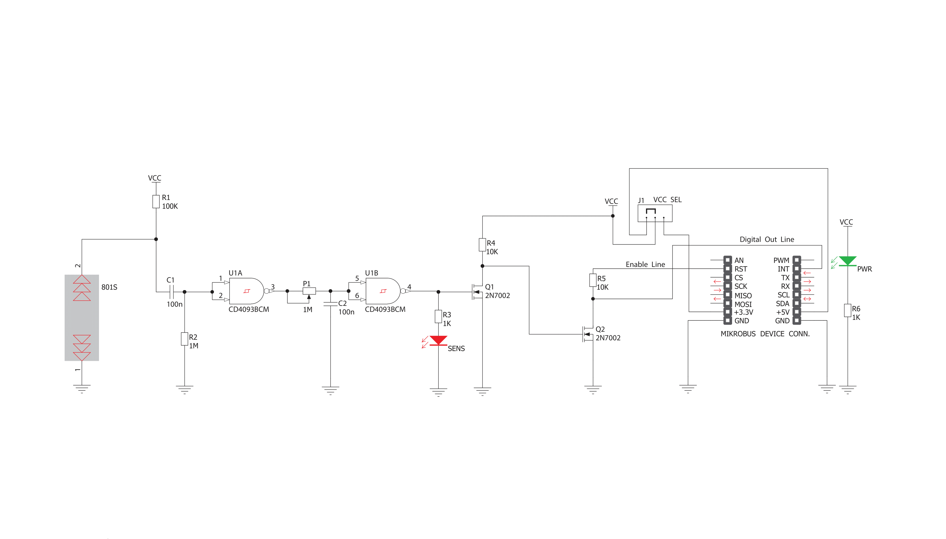
Vibra sense Click is based on the 801S, a shock sensor from Sencera. To eliminate signal noise, the sensor's output uses a pull-up configuration alongside quad 2-input NAND Schmitt Trigger, the CD4093BC from ON Semiconductor, which is necessary as the output must become a square wave. Two of its 2-input gates and the potentiometer are used to clean the noise and set the interrupt threshold. With this potentiometer, you can set the force necessary to activate the Vibra sense Click. The sensor is extremely sensitive
to movements such as a light tap or vibration. Unlike many other sensors that use a mechanical switching element, this one uses a resistive element that changes resistance with motion. The Vibra Sense Click uses digital output over interrupt dedicated pin INT to communicate to the host MCU over a mikroBUS™ socket. In addition, this Click board™ features EN, an enable pin that lets you turn off the outputs of the 801S sensor. For a visual presentation of shock detection, this Click board™ features a VIBRA LED that will light
according to the vibration and the potentiometer-set threshold. This Click board™ can operate with either 3.3V or 5V logic voltage levels selected via the VCC SEL jumper. This way, both 3.3V and 5V capable MCUs can use the communication lines properly. Also, this Click board™ comes equipped with a library containing easy-to-use functions and an example code that can be used as a reference for further development.

Features overview
Development board
UNI-DS v8 is a development board specially designed for the needs of rapid development of embedded applications. It supports a wide range of microcontrollers, such as different STM32, Kinetis, TIVA, CEC, MSP, PIC, dsPIC, PIC32, and AVR MCUs regardless of their number of pins, and a broad set of unique functions, such as the first-ever embedded debugger/programmer over WiFi. The development board is well organized and designed so that the end-user has all the necessary elements, such as switches, buttons, indicators, connectors, and others, in one place. Thanks to innovative manufacturing technology, UNI-DS v8 provides a fluid and immersive working experience, allowing access anywhere and under any
circumstances at any time. Each part of the UNI-DS v8 development board contains the components necessary for the most efficient operation of the same board. An advanced integrated CODEGRIP programmer/debugger module offers many valuable programming/debugging options, including support for JTAG, SWD, and SWO Trace (Single Wire Output)), and seamless integration with the Mikroe software environment. Besides, it also includes a clean and regulated power supply module for the development board. It can use a wide range of external power sources, including a battery, an external 12V power supply, and a power source via the USB Type-C (USB-C) connector. Communication options such as USB-UART, USB
HOST/DEVICE, CAN (on the MCU card, if supported), and Ethernet is also included. In addition, it also has the well-established mikroBUS™ standard, a standardized socket for the MCU card (SiBRAIN standard), and two display options for the TFT board line of products and character-based LCD. UNI-DS v8 is an integral part of the Mikroe ecosystem for rapid development. Natively supported by Mikroe software tools, it covers many aspects of prototyping and development thanks to a considerable number of different Click boards™ (over a thousand boards), the number of which is growing every day.

Microcontroller Overview
MCU Card / MCU
Type
8th Generation
Architecture
ARM Cortex-M4
MCU Memory (KB)
2048
Silicon Vendor
STMicroelectronics
Pin count
216
RAM (Bytes)
262144
Used MCU Pins
mikroBUS™ mapper
Take a closer look
Click board™ Schematic
Step by step
Project assembly

Start by selecting your development board and Click board™. Begin with the UNI-DS v8 as your development board.


Track your results in real time
Application Output
1. Application Output - In Debug mode, the 'Application Output' window enables real-time data monitoring, offering direct insight into execution results. Ensure proper data display by configuring the environment correctly using the provided tutorial.

2. UART Terminal - Use the UART Terminal to monitor data transmission via a USB to UART converter, allowing direct communication between the Click board™ and your development system. Configure the baud rate and other serial settings according to your project's requirements to ensure proper functionality. For step-by-step setup instructions, refer to the provided tutorial.

3. Plot Output - The Plot feature offers a powerful way to visualize real-time sensor data, enabling trend analysis, debugging, and comparison of multiple data points. To set it up correctly, follow the provided tutorial, which includes a step-by-step example of using the Plot feature to display Click board™ readings. To use the Plot feature in your code, use the function: plot(*insert_graph_name*, variable_name);. This is a general format, and it is up to the user to replace 'insert_graph_name' with the actual graph name and 'variable_name' with the parameter to be displayed.

Software Support
Library Description
This library contains API for Vibra sense Click driver.
Key functions:
vibrasense_check_interrupt- Check interrupt functionvibrasense_reset- Reset vibra sense function
Open Source
Code example
The complete application code and a ready-to-use project are available through the NECTO Studio Package Manager for direct installation in the NECTO Studio. The application code can also be found on the MIKROE GitHub account.
/*!
 * \file
 * \brief Vibra sense Click example
 *
 * # Description
 * This is a example which demonstrates the use of Vibra sense Click board.
 *
 * The demo application is composed of two sections :
 *
 * ## Application Init
 * Configuring Clicks and log objects.
 *
 * ## Application Task
 * It detects vibrations and enables PWM and writes log according to them.
 *
 * \author MikroE Team
 *
 */
// ------------------------------------------------------------------- INCLUDES

#include "board.h"
#include "log.h"
#include "vibrasense.h"

// ------------------------------------------------------------------ VARIABLES

static vibrasense_t vibrasense;
static log_t logger;

// ------------------------------------------------------- ADDITIONAL FUNCTIONS


// ------------------------------------------------------ APPLICATION FUNCTIONS


void application_init ( void )
{
    log_cfg_t log_cfg;
    vibrasense_cfg_t cfg;

    /**
     * Logger initialization.
     * Default baud rate: 115200
     * Default log level: LOG_LEVEL_DEBUG
     * @note If USB_UART_RX and USB_UART_TX
     * are defined as HAL_PIN_NC, you will
     * need to define them manually for log to work.
     * See @b LOG_MAP_USB_UART macro definition for detailed explanation.
     */
    LOG_MAP_USB_UART( log_cfg );
    log_init( &logger, &log_cfg );
    log_printf(&logger, "- Application Init -\r\n");

    //  Click initialization.

    vibrasense_cfg_setup( &cfg );
    VIBRASENSE_MAP_MIKROBUS( cfg, MIKROBUS_1 );
    vibrasense_init( &vibrasense, &cfg );
    Delay_ms ( 100 );

    log_printf(&logger, "--------------------\r\n");
    log_printf(&logger, "  Vibra sense Click \r\n");
    log_printf(&logger, "--------------------\r\n");

    vibrasense_set_mode( &vibrasense, VIBRASENSE_ENABLE );
    Delay_ms ( 100 );
}

void application_task ( void )
{
    if ( vibrasense_check_interrupt( &vibrasense ) )
    {
        log_printf(&logger, "       TILT !!!     \r\n");
        log_printf(&logger, "--------------------\r\n");
        Delay_ms ( 100 );
    }
}


int main ( void )
{
    /* Do not remove this line or clock might not be set correctly. */
    #ifdef PREINIT_SUPPORTED
    preinit();
    #endif

    application_init( );

    for ( ; ; )
    {
        application_task( );
    }

    return 0;
}


// ------------------------------------------------------------------------ END