Capture, analyze, and optimize movement with ADXL314 and STM32L496AG like never before
Unraveling motion's secrets in every direction

Published Jul 22, 2025
Click board™
Accel 29 Click
Dev. board
Discovery kit with STM32L496AG MCU
Compiler
NECTO Studio
MCU
STM32L496AG
Elevate your projects and enhance connectivity with our 3D accelerometer, ushering in an era of improved data accuracy and responsiveness
A
A
Hardware Overview
How does it work?
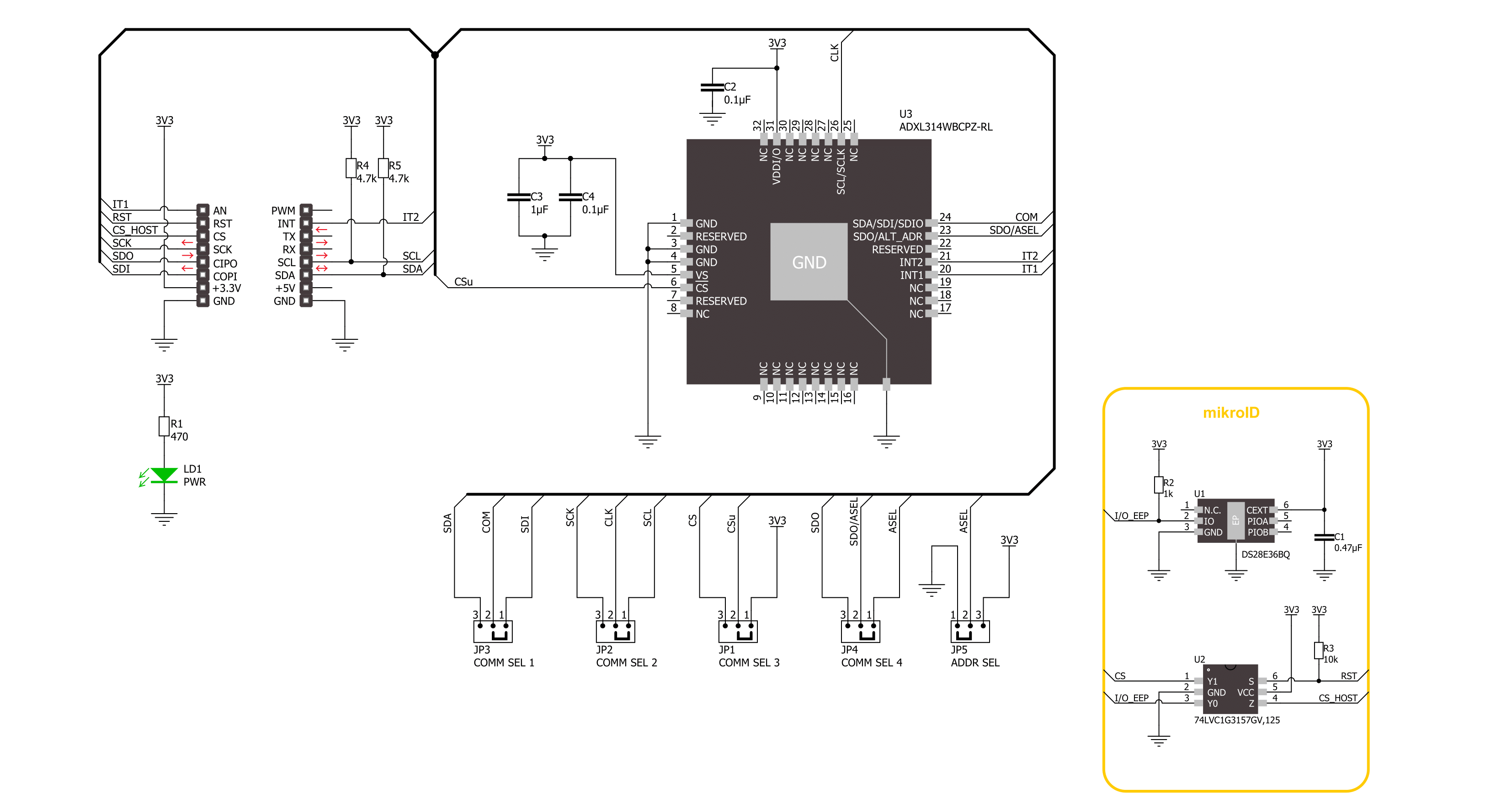
Accel 29 Click is based on the ADXL314, a complete three-axis ±200g acceleration measurement system from Analog Devices, operating at low power levels. The ADXL314 measures both dynamic accelerations resulting from motion or shock and static accelerations, such as gravity. It provides digital output data formatted as 16-bit, with acceleration reported digitally through a configurable and selectable serial interface. The ADXL314 automatically modulates its power consumption proportionately to its output data rate. If additional power savings are desired, it also offers lower power modes, enabling intelligent motion-based power management with threshold sensing and active acceleration measurement at low power dissipation. The ADXL314 is based on a polysilicon surface-micromachined structure built on top of a silicon wafer that suspends the
structure over the surface of the wafer, providing resistance against forces due to applied acceleration. Deflection of the structure is measured using differential capacitors that consist of independent fixed plates and plates attached to the moving mass. Acceleration deflects the proof mass and unbalances the differential capacitor, producing a sensor output whose amplitude is proportional to acceleration. Phase-sensitive demodulation is used to determine the magnitude and polarity of the acceleration. As mentioned, the acceleration data is accessed through the I2C or SPI interface with a maximum frequency of 400kHz for I2C and 5MHz for SPI communication. The selection is made by positioning SMD jumpers labeled COMM SEL appropriately. Note that all the jumpers' positions must be on the same side, or the Click board™
may become unresponsive. While the I2C interface is selected, the ADXL314 allows choosing the least significant bit (LSB) of its I2C slave address using the SMD jumper labeled ADDR SEL. This board also possesses two interrupts, IT1 and IT2, routed to, where, by default, the AN and IT pins stand on the mikroBUS™ socket, entirely programmed by the user through a serial interface. They signal MCU that a motion event has been sensed. This Click board™ can be operated only with a 3.3V logic voltage level. The board must perform appropriate logic voltage level conversion before using MCUs with different logic levels. Also, it comes equipped with a library containing functions and an example code that can be used as a reference for further development.


Features overview
Development board
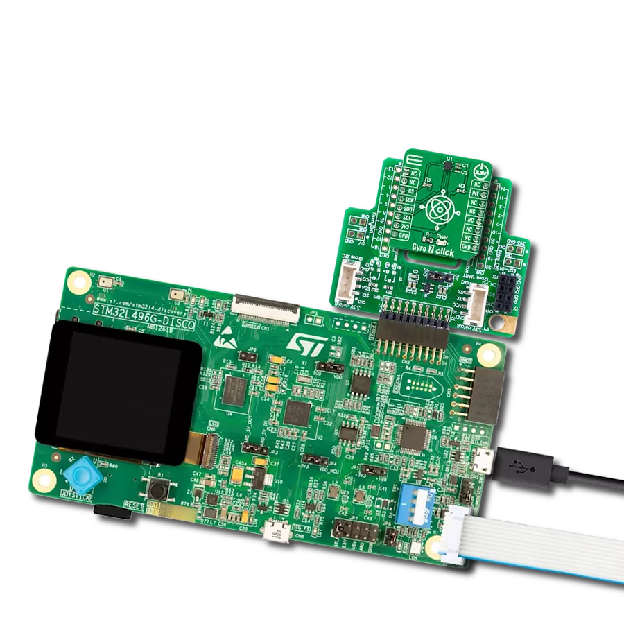
The 32L496GDISCOVERY Discovery kit serves as a comprehensive demonstration and development platform for the STM32L496AG microcontroller, featuring an Arm® Cortex®-M4 core. Designed for applications that demand a balance of high performance, advanced graphics, and ultra-low power consumption, this kit enables seamless prototyping for a wide range of embedded solutions. With its innovative energy-efficient
architecture, the STM32L496AG integrates extended RAM and the Chrom-ART Accelerator, enhancing graphics performance while maintaining low power consumption. This makes the kit particularly well-suited for applications involving audio processing, graphical user interfaces, and real-time data acquisition, where energy efficiency is a key requirement. For ease of development, the board includes an onboard ST-LINK/V2-1
debugger/programmer, providing a seamless out-of-the-box experience for loading, debugging, and testing applications without requiring additional hardware. The combination of low power features, enhanced memory capabilities, and built-in debugging tools makes the 32L496GDISCOVERY kit an ideal choice for prototyping advanced embedded systems with state-of-the-art energy efficiency.

Microcontroller Overview
MCU Card / MCU

Architecture
ARM Cortex-M4
MCU Memory (KB)
1024
Silicon Vendor
STMicroelectronics
Pin count
169
RAM (Bytes)
327680
Used MCU Pins
mikroBUS™ mapper
Take a closer look
Click board™ Schematic
Step by step
Project assembly

Start by selecting your development board and Click board™. Begin with the Discovery kit with STM32L496AG MCU as your development board.


Track your results in real time
Application Output
1. Application Output - In Debug mode, the 'Application Output' window enables real-time data monitoring, offering direct insight into execution results. Ensure proper data display by configuring the environment correctly using the provided tutorial.

2. UART Terminal - Use the UART Terminal to monitor data transmission via a USB to UART converter, allowing direct communication between the Click board™ and your development system. Configure the baud rate and other serial settings according to your project's requirements to ensure proper functionality. For step-by-step setup instructions, refer to the provided tutorial.

3. Plot Output - The Plot feature offers a powerful way to visualize real-time sensor data, enabling trend analysis, debugging, and comparison of multiple data points. To set it up correctly, follow the provided tutorial, which includes a step-by-step example of using the Plot feature to display Click board™ readings. To use the Plot feature in your code, use the function: plot(*insert_graph_name*, variable_name);. This is a general format, and it is up to the user to replace 'insert_graph_name' with the actual graph name and 'variable_name' with the parameter to be displayed.

Software Support
Library Description
This library contains API for Accel 29 Click driver.
Key functions:
accel29_calibrate_offset- This function calibrates accel offset to the specified values by setting the OFSX/Y/Z registersaccel29_get_avg_axes- This function reads a specified number of samples for accel X, Y, and Z axis data in g and averages them
Open Source
Code example
The complete application code and a ready-to-use project are available through the NECTO Studio Package Manager for direct installation in the NECTO Studio. The application code can also be found on the MIKROE GitHub account.
/*!
 * @file main.c
 * @brief Accel 29 Click example
 *
 * # Description
 * This example demonstrates the use of Accel 29 Click board by reading and
 * displaying the accelerometer data (X, Y, and Z axis) averaged from 100 samples.
 *
 * The demo application is composed of two sections :
 *
 * ## Application Init
 * Initializes the driver, performs the Click default configuration, and calibrates
 * the accel data offsets.
 *
 * ## Application Task
 * Reads and displays on the USB UART the accelerometer data (X, Y, and Z axis)
 * averaged from 100 samples.
 *
 * @note
 * This Click board should be used for high g applications of up to +-200g.
 * It is not recommended for low g applications because of its high scale
 * factor which is about 48.83 mg per LSB.
 *
 * @author Stefan Filipovic
 *
 */

#include "board.h"
#include "log.h"
#include "accel29.h"

/**
 * Starting accel position, used for calibrating accel offset.
 * Should be in a range from -24.96 to 24.765 g.
 * Offset calibrating scale factor is 0.195 g per LSB.
 */
#define ACCEL29_CALIB_X     0.0f
#define ACCEL29_CALIB_Y     0.0f
#define ACCEL29_CALIB_Z     1.0f

static accel29_t accel29;
static log_t logger;

void application_init ( void )
{
    log_cfg_t log_cfg;  /**< Logger config object. */
    accel29_cfg_t accel29_cfg;  /**< Click config object. */

    /**
     * Logger initialization.
     * Default baud rate: 115200
     * Default log level: LOG_LEVEL_DEBUG
     * @note If USB_UART_RX and USB_UART_TX
     * are defined as HAL_PIN_NC, you will
     * need to define them manually for log to work.
     * See @b LOG_MAP_USB_UART macro definition for detailed explanation.
     */
    LOG_MAP_USB_UART( log_cfg );
    log_init( &logger, &log_cfg );
    log_info( &logger, " Application Init " );

    // Click initialization.
    accel29_cfg_setup( &accel29_cfg );
    ACCEL29_MAP_MIKROBUS( accel29_cfg, MIKROBUS_1 );
    err_t init_flag = accel29_init( &accel29, &accel29_cfg );
    if ( ( I2C_MASTER_ERROR == init_flag ) || ( SPI_MASTER_ERROR == init_flag ) )
    {
        log_error( &logger, " Communication init." );
        for ( ; ; );
    }

    if ( ACCEL29_ERROR == accel29_default_cfg ( &accel29 ) )
    {
        log_error( &logger, " Default configuration." );
        for ( ; ; );
    }

    accel29_axes_t calib_axes;
    calib_axes.x = ACCEL29_CALIB_X;
    calib_axes.y = ACCEL29_CALIB_Y;
    calib_axes.z = ACCEL29_CALIB_Z;
    if ( ACCEL29_ERROR == accel29_calibrate_offset ( &accel29, calib_axes ) )
    {
        log_error( &logger, " Calibrate offset." );
        for ( ; ; );
    }

    log_info( &logger, " Application Task " );
}

void application_task ( void )
{
    accel29_axes_t axes;
    if ( ACCEL29_OK == accel29_get_avg_axes ( &accel29, ACCEL29_NUM_OF_SAMPLES, &axes ) )
    {
        log_printf( &logger, " X: %.1f g\r\n", axes.x );
        log_printf( &logger, " Y: %.1f g\r\n", axes.y );
        log_printf( &logger, " Z: %.1f g\r\n\n", axes.z );
    }
}

int main ( void )
{
    /* Do not remove this line or clock might not be set correctly. */
    #ifdef PREINIT_SUPPORTED
    preinit();
    #endif

    application_init( );

    for ( ; ; )
    {
        application_task( );
    }

    return 0;
}

// ------------------------------------------------------------------------ END
Additional Support
Resources
Category:Motion