Respond to every move with ADXL363 and PIC18F85J50
Sensors that amplify your motion

Published Oct 05, 2023
Click board™
Accel 16 Click
Dev. board
Fusion for PIC v8
Compiler
NECTO Studio
MCU
PIC18F85J50
This solution enables precise motion tracking, allowing for the evaluation of physical movements, vibrations, and changes in position
A
A
Hardware Overview
How does it work?
Accel 16 Click is based on the ADXL363, a micropower complete sensor suite consisting of an accelerometer, an ADC for synchronous input conversion from a third sensor, and a temperature sensor from Analog Devices. It measures both dynamic accelerations, resulting from motion or shock, and static acceleration, such as tilt, and allows selectable full-scale acceleration measurements in ranges of ±2g, ±4g, and ±8g (with a resolution of 1mg/LSB on the ±2g range). Acceleration is reported digitally, and the device communicates via the SPI protocol, providing 12-bit output resolution for all three sensors. The ADXL363 has two operating modes: Measurement mode for continuous, wide-bandwidth sensing and Wake-up mode for limited bandwidth activity detection. Measurement mode represents its normal operating mode, and in this mode, acceleration data is read continuously, while the Wake-Up mode is ideal for simple detection of the presence or absence of motion at low power
consumption. Wake-up mode helps implement a motion-activated ON/OFF switch, allowing the rest of the system to power down until the activity is detected. In addition, measurement is suspended altogether by placing the device in Standby mode, reducing current consumption. During Standby, pending interrupts and data are preserved, and no new interrupts are generated. In addition to a built-in accelerometer and temperature sensor, which the user can use to monitor internal system temperature or improve the device's temperature stability via calibration, the ADXL363 incorporates a 12-bit analog-to-digital converter (ADC) for digitization of external analog input. The ADC converts analog inputs ranging from 10% to 90% of the supply voltage and is best suited for sensor input due to its synchronization with the accelerometer and temperature sensor. The ADXL363 communicates with MCU through a standard SPI interface that enables clock speeds up to 8MHz, supporting the most common
SPI mode - SPI Mode 0. This Click board™ also possesses two interrupt pins, INT1 and INT2, routed to the INT and PWM pins on the mikroBUS™, which have a dual function. First, they can be used as classic interrupt pins to signal MCU that an event has been sensed or can be used, e.g., INT1 as an input for external clocking and INT2 as input for synchronized sampling. One or both of these alternate functions can be used concurrently; however, if an interrupt pin is used for its alternate function, it cannot simultaneously be used for its primary function, to signal interrupts. This Click board™ can be operated only with a 3.3V logic voltage level. The board must perform appropriate logic voltage level conversion before using MCUs with different logic levels. Also, it comes equipped with a library containing functions and an example code that can be used as a reference for further development.

Features overview
Development board
Fusion for PIC v8 is a development board specially designed for the needs of rapid development of embedded applications. It supports a wide range of microcontrollers, such as different PIC, dsPIC, PIC24, and PIC32 MCUs regardless of their number of pins, and a broad set of unique functions, such as the first-ever embedded debugger/programmer over WiFi. The development board is well organized and designed so that the end-user has all the necessary elements, such as switches, buttons, indicators, connectors, and others, in one place. Thanks to innovative manufacturing technology, Fusion for PIC v8 provides a fluid and immersive working experience, allowing access anywhere and under any
circumstances at any time. Each part of the Fusion for PIC v8 development board contains the components necessary for the most efficient operation of the same board. In addition to the advanced integrated CODEGRIP programmer/debugger module, which offers many valuable programming/debugging options and seamless integration with the Mikroe software environment, the board also includes a clean and regulated power supply module for the development board. It can use a wide range of external power sources, including a battery, an external 12V power supply, and a power source via the USB Type-C (USB-C) connector. Communication options such as USB-UART, USB
HOST/DEVICE, CAN (on the MCU card, if supported), and Ethernet are also included, including the well-established mikroBUS™ standard, a standardized socket for the MCU card (SiBRAIN standard), and two display options (graphical and character-based LCD). Fusion for PIC v8 is an integral part of the Mikroe ecosystem for rapid development. Natively supported by Mikroe software tools, it covers many aspects of prototyping and development thanks to a considerable number of different Click boards™ (over a thousand boards), the number of which is growing every day.

Microcontroller Overview
MCU Card / MCU
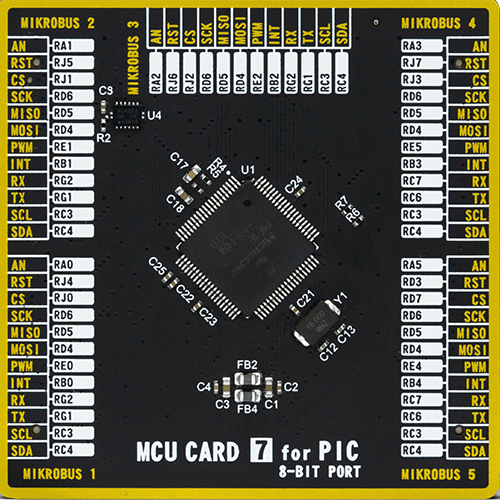
Type
8th Generation
Architecture
PIC
MCU Memory (KB)
32
Silicon Vendor
Microchip
Pin count
80
RAM (Bytes)
3904
Used MCU Pins
mikroBUS™ mapper
Take a closer look
Click board™ Schematic

Step by step
Project assembly

Start by selecting your development board and Click board™. Begin with the Fusion for PIC v8 as your development board.


Track your results in real time
Application Output
1. Application Output - In Debug mode, the 'Application Output' window enables real-time data monitoring, offering direct insight into execution results. Ensure proper data display by configuring the environment correctly using the provided tutorial.

2. UART Terminal - Use the UART Terminal to monitor data transmission via a USB to UART converter, allowing direct communication between the Click board™ and your development system. Configure the baud rate and other serial settings according to your project's requirements to ensure proper functionality. For step-by-step setup instructions, refer to the provided tutorial.

3. Plot Output - The Plot feature offers a powerful way to visualize real-time sensor data, enabling trend analysis, debugging, and comparison of multiple data points. To set it up correctly, follow the provided tutorial, which includes a step-by-step example of using the Plot feature to display Click board™ readings. To use the Plot feature in your code, use the function: plot(*insert_graph_name*, variable_name);. This is a general format, and it is up to the user to replace 'insert_graph_name' with the actual graph name and 'variable_name' with the parameter to be displayed.

Software Support
Library Description
This library contains API for Accel 16 Click driver.
Key functions:
accel16_get_axes- Get axes dataaccel16_filter_configuration- Filter configurationaccel16_get_temperature- Get temperature data
Open Source
Code example
The complete application code and a ready-to-use project are available through the NECTO Studio Package Manager for direct installation in the NECTO Studio. The application code can also be found on the MIKROE GitHub account.
/*!
 * @file main.c
 * @brief Accel16 Click example
 *
 * # Description
 * This showcases ability of the Click board to
 * read x, y, and z axes data in different resolution,
 * read IC temperature and also have additional functionality
 * to read ADC data. Device also has ability to store data
 * in internal fifo buffer.
 *
 * The demo application is composed of two sections :
 *
 * ## Application Init
 * Initialization of communication modules(SPI, UART) and
 * additional interrupt pins. Reads device ID's and revision.
 * Then configures device to work in FIFO mode or to read data
 * from the registers, sets 2g resolution, 12.5Hz output data rate,
 * sets interrupt 1 active low, powers on device, and calibrates temperature.
 *
 * ## Application Task
 * Depending of the application mode selects example.
 *  - If fifo example is selected waits for the interrupt
 *      to indicate that data is ready  in fifo buffer and
 *      reads number of fifo entries. Data that should be
 *      read are X, Y, Z axes and temperature.
 *  - If register example is selected also waits for interrupt
 *      to indicate that data is ready to read. Then reads X, Y, Z
 *      axes, temperature, and ADC data.
 *
 * @author Luka Filipovic
 *
 */

#include "board.h"
#include "log.h"
#include "accel16.h"
#include "conversions.h"

static accel16_t accel16;
static log_t logger;

/**
 * @brief Fifo read data example.
 * @details This function waits for new data in fifo buffer, reads
 * number of fifo enries and reads that amount of fifo bytes multiple by 2.
 * Goes through the buffer and logs data.
 * @return Nothing.
 */
static void accel16_read_fifo_data ( void );

/**
 * @brief Register data read example.
 * @details This function waits for new data indication and reads axes, temperature
 * and ADC data and logs result.
 * @return Nothing.
 */
static void accel16_read_reg_data ( void );

void application_init ( void )
{
    log_cfg_t log_cfg;  /**< Logger config object. */
    accel16_cfg_t accel16_cfg;  /**< Click config object. */

    /**
     * Logger initialization.
     * Default baud rate: 115200
     * Default log level: LOG_LEVEL_DEBUG
     * @note If USB_UART_RX and USB_UART_TX
     * are defined as HAL_PIN_NC, you will
     * need to define them manually for log to work.
     * See @b LOG_MAP_USB_UART macro definition for detailed explanation.
     */
    LOG_MAP_USB_UART( log_cfg );
    log_init( &logger, &log_cfg );
    log_info( &logger, " Application Init " );

    // Click initialization.
    accel16_cfg_setup( &accel16_cfg );
    ACCEL16_MAP_MIKROBUS( accel16_cfg, MIKROBUS_1 );
    if ( SPI_MASTER_ERROR == accel16_init( &accel16, &accel16_cfg ) )
    {
        log_error( &logger, " Communication init." );
        for ( ; ; );
    }

    accel16.application_type = ACCEL16_APPLICATION_REG;

    uint8_t temp_buf[ 4 ] = { 0 };

    accel16_multiple_reg_read( &accel16, ACCEL16_REG_DEVID_AD, temp_buf, 4 );
    log_printf( &logger, " > ID0: 0x%.2X\r\n > ID1: 0x%.2X\r\n > ID2: 0x%.2X\r\n > REV: 0x%.2X\r\n",
                ( uint16_t ) temp_buf[ 0 ], ( uint16_t ) temp_buf[ 1 ],
                ( uint16_t ) temp_buf[ 2 ], ( uint16_t ) temp_buf[ 3 ] );

    if ( ACCEL16_ERROR == accel16_default_cfg ( &accel16 ) )
    {
        log_error( &logger, " Default configuration." );
        for ( ; ; );
    }

    log_info( &logger, " Application Task " );
}

void application_task ( void )
{
    if ( ACCEL16_APPLICATION_FIFO == accel16.application_type )
    {
        accel16_read_fifo_data( );
    }
    else if ( ACCEL16_APPLICATION_REG == accel16.application_type )
    {
        accel16_read_reg_data( );
    }

    log_printf( &logger, "********************************************************\r\n" );
}

int main ( void )
{
    /* Do not remove this line or clock might not be set correctly. */
    #ifdef PREINIT_SUPPORTED
    preinit();
    #endif

    application_init( );

    for ( ; ; )
    {
        application_task( );
    }

    return 0;
}

static void accel16_read_fifo_data ( void )
{
    uint8_t temp_buf[ 1024 ] = { 0 };
    int16_t temp_data = 0;

    while ( accel16_get_interrupt_1( &accel16 ) );

    accel16_multiple_reg_read( &accel16, ACCEL16_REG_FIFO_ENTRIES_L, temp_buf, 2 );
    uint16_t fifo_entries = ( ( uint16_t )temp_buf[ 1 ] << 8 ) | temp_buf[ 0 ];
    fifo_entries &= 0x03FF;

    accel16_fifo_read( &accel16, temp_buf, fifo_entries * 2 );

    for ( uint16_t cnt = 0; cnt < fifo_entries * 2; cnt += 2 )
    {
        temp_data = ( ( uint16_t )temp_buf[ cnt + 1 ] << 8 ) | temp_buf[ cnt ];
        uint8_t fifo_data = ( temp_data >> 14 ) & 0x3;
        temp_data &= 0x3FFF;
        temp_data <<= 2;
        temp_data >>= 2;

        switch ( fifo_data )
        {
            case 0x0:
            {
                log_printf( &logger, " > X[g]: %d\r\n", temp_data );
                break;
            }
            case 0x1:
            {
                log_printf( &logger, " > Y[g]: %d\r\n", temp_data );
                break;
            }
            case 0x2:
            {
                log_printf( &logger, " > Z[g]: %d\r\n", temp_data );
                break;
            }
            case 0x3:
            {
                float temperature = ACCEL16_ROOM_TEMPERATURE +
                                    ( temp_data - ACCEL16_TEMPERATURE_BIAS ) * ACCEL16_TEMPERATURE_RES -
                                    accel16.room_temp_offset;;
                log_printf( &logger, " > Temperature[degC]: %.2f\r\n", temperature );
                break;
            }
            default:
            {
                log_error( &logger, "Fifo data!" );
                break;
            }
        }
    }
}

static void accel16_read_reg_data ( void )
{
    uint8_t temp_byte = 0;
    float temperature = 0;
    float adc = 0;
    accel16_axes_t axes;

    while ( accel16_get_interrupt_1( &accel16 ) );

    accel16_get_axes ( &accel16, &axes );
    accel16_get_temperature ( &accel16, &temperature );
    accel16_get_adc ( &accel16, &adc );

    log_printf( &logger, " > X[g]: %.2f\r\n", axes.x );
    log_printf( &logger, " > Y[g]: %.2f\r\n", axes.y );
    log_printf( &logger, " > Z[g]: %.2f\r\n", axes.z );
    log_printf( &logger, " > Temperature[degC]: %.2f\r\n", temperature );
    log_printf( &logger, " > ADC[V]: %.2f\r\n", adc );
}

// ------------------------------------------------------------------------ END


