Empower your projects with the magic of 6DoF IMU using BMI270 and STM32L496AG
Move beyond limits: Unleash the power of 6-axis motion sensing

Published Jul 22, 2025
Click board™
6DOF IMU 12 Click
Dev. board
Discovery kit with STM32L496AG MCU
Compiler
NECTO Studio
MCU
STM32L496AG
Our 6DoF IMU solution is designed to revolutionize motion tracking, offering unparalleled accuracy and responsiveness for a wide range of applications
A
A
Hardware Overview
How does it work?
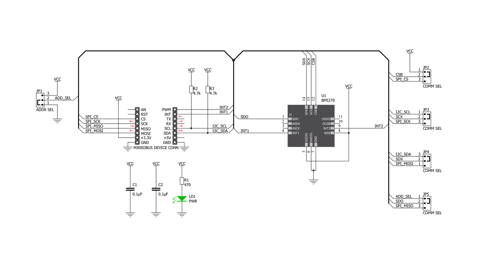
6DOF IMU 12 Click is based on the BMI270, an ultra-low-power IMU optimized for wearable applications from Bosch Sensortec. The IMU combines precise acceleration and angular rate measurement with intelligent on-chip motion-triggered interrupt features. The 6-axis sensor combines a 16-bit triaxial gyroscope and a 16-bit triaxial accelerometer in a compact 2.5x3.0x0.8mm LGA package. BMI270 is a member of Bosch Sensortec’s BMI260 family of IMUs, targeting fast and accurate inertial sensing in wearable applications. It also features Bosch’s automotive-proven gyroscope technology with an improved accelerometer. Significant improvements in BMI270 include, but are not restricted to, the overall accelerometer performance, i.e. an extremely low zero-g offset and sensitivity error, low temperature drifts, robustness over PCB strain and a low noise density. It also features the industry’s first self-calibrating gyroscope using motionless CRT (Component Re-Trimming) functionality to compensate MEMS typical soldering drifts, ensuring post-soldering sensitivity
errors down to ± 0.4%. BMI270 includes intuitive gesture, context and activity recognition with an integrated plug-and-play step counter/detector, which is optimized for accurate step counting in wrist-worn devices. The IMU is also well suited for other types of wearable devices, such as hearables, smart clothes, smart shoes, smart glasses and ankle bands. The smart IMU has a wide range for VDD and VDDIO supply voltages. The performance and current consumption are stable over the entire supply range. Typical current draw for BMI270’s accelerometer and gyroscope at full ODR of 6.4 kHz is under 700μA. By enabling high output data rates with low current consumption, wearable manufacturers can avoid an unpleasant aliasing effect – an effect that causes different signals to become indistinguishable when sampled at lower ODRs. Bosch Sensortec’s ultra-low-power IMU BMI270 provides an intelligent power management system enabling motion-triggered always-on features to run inside the ultra-low-power domain of the IMU. BMI270 significantly extends system battery life by
handling multiple activity tracking, step counting and gesture recognition functions independently of the main system processor, without having to wake it up. The processor-independent functions include tasks such as sending an interrupt when a certain number of steps is reached, or geofencing to activate GPS when the user stands up and starts walking. The device features I2C and SPI serial interfaces, a VDD operating range from 1.71V to 3.6V, and a separate digital IO supply (VDDIO) from 1.2V to 3.6V. Communication with all registers of the device can be performed using either SPI at 10MHz or I2C at up to 1MHz. 6DOF IMU 12 Click supports both SPI and I2C communication interfaces, allowing it to be used with a wide range of different MCUs. The communication interface can be selected by moving SMD jumpers grouped under the COM SEL to an appropriate position (SPI or I2C). The slave I2C address can also be configured by an SMD jumper when the Click board™ is operated in the I2C mode. An SMD jumper labeled as ADD SEL is used to set the least significant bit (LSB) of the I2C address.


Features overview
Development board
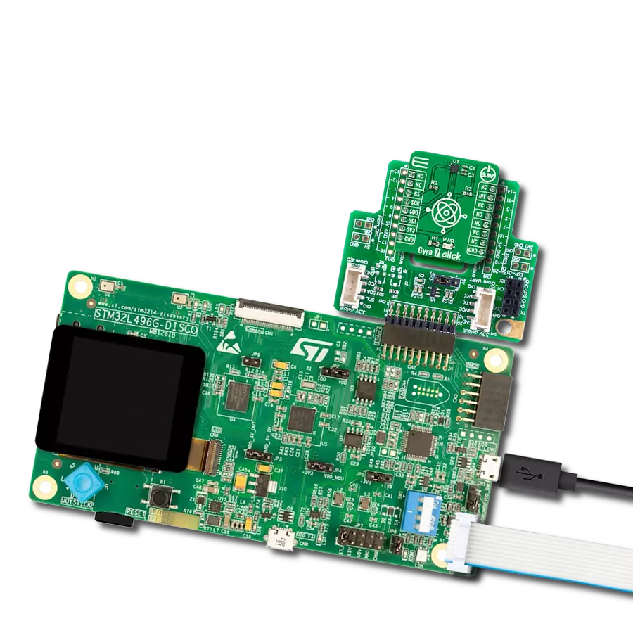
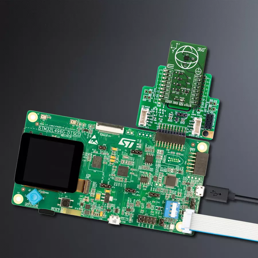
The 32L496GDISCOVERY Discovery kit serves as a comprehensive demonstration and development platform for the STM32L496AG microcontroller, featuring an Arm® Cortex®-M4 core. Designed for applications that demand a balance of high performance, advanced graphics, and ultra-low power consumption, this kit enables seamless prototyping for a wide range of embedded solutions. With its innovative energy-efficient
architecture, the STM32L496AG integrates extended RAM and the Chrom-ART Accelerator, enhancing graphics performance while maintaining low power consumption. This makes the kit particularly well-suited for applications involving audio processing, graphical user interfaces, and real-time data acquisition, where energy efficiency is a key requirement. For ease of development, the board includes an onboard ST-LINK/V2-1
debugger/programmer, providing a seamless out-of-the-box experience for loading, debugging, and testing applications without requiring additional hardware. The combination of low power features, enhanced memory capabilities, and built-in debugging tools makes the 32L496GDISCOVERY kit an ideal choice for prototyping advanced embedded systems with state-of-the-art energy efficiency.

Microcontroller Overview
MCU Card / MCU

Architecture
ARM Cortex-M4
MCU Memory (KB)
1024
Silicon Vendor
STMicroelectronics
Pin count
169
RAM (Bytes)
327680
Used MCU Pins
mikroBUS™ mapper
Take a closer look
Click board™ Schematic
Step by step
Project assembly

Start by selecting your development board and Click board™. Begin with the Discovery kit with STM32L496AG MCU as your development board.


Track your results in real time
Application Output
1. Application Output - In Debug mode, the 'Application Output' window enables real-time data monitoring, offering direct insight into execution results. Ensure proper data display by configuring the environment correctly using the provided tutorial.

2. UART Terminal - Use the UART Terminal to monitor data transmission via a USB to UART converter, allowing direct communication between the Click board™ and your development system. Configure the baud rate and other serial settings according to your project's requirements to ensure proper functionality. For step-by-step setup instructions, refer to the provided tutorial.

3. Plot Output - The Plot feature offers a powerful way to visualize real-time sensor data, enabling trend analysis, debugging, and comparison of multiple data points. To set it up correctly, follow the provided tutorial, which includes a step-by-step example of using the Plot feature to display Click board™ readings. To use the Plot feature in your code, use the function: plot(*insert_graph_name*, variable_name);. This is a general format, and it is up to the user to replace 'insert_graph_name' with the actual graph name and 'variable_name' with the parameter to be displayed.

Software Support
Library Description
This library contains API for 6DOF IMU 12 Click driver.
Key functions:
c6dofimu12_check_id- Function check status initialization of the device of BMI270 6-axis, smart, low-power Inertial Measurement on 6DOF IMU 12 Clickc6dofimu12_check_init_status- Function check status initialization of the device of BMI270 6-axis, smart, low-power Inertial Measurement on 6DOF IMU 12 Clickc6dofimu12_get_data- Function reads Accel and Gyro 16-bit ( signed ) X-axis, Y-axis data and Z-axis data from the 12 targeted starts from C6DOFIMU12_REG_ACC_X_LSB_ADDR register address of BMI270 6-axis, smart, low-power Inertial Measurement on 6DOF IMU 12 Click
Open Source
Code example
The complete application code and a ready-to-use project are available through the NECTO Studio Package Manager for direct installation in the NECTO Studio. The application code can also be found on the MIKROE GitHub account.
/*!
 * \file
 * \brief C6DofImu12 Click example
 *
 * # Description
 * This example demonstrates the use of 6DOF IMU 12 Click board.
 *
 * The demo application is composed of two sections :
 *
 * ## Application Init
 * Initializes the driver and checks the communication then initializes the device
 * and sets the device default configuration.
 *
 * ## Application Task
 * Measures acceleration and gyroscope data and displays the results on USB UART each second.
 *
 * \author MikroE Team
 *
 */
// ------------------------------------------------------------------- INCLUDES

#include "board.h"
#include "log.h"
#include "c6dofimu12.h"
#include "c6dofimu12_config.h"

// ------------------------------------------------------------------ VARIABLES

static c6dofimu12_t c6dofimu12;
static c6dofimu12_accel_t c6dofimu12_accel;
static c6dofimu12_gyro_t c6dofimu12_gyro;

static log_t logger;

// ------------------------------------------------------ APPLICATION FUNCTIONS

void application_init ( void )
{
    uint8_t tx_buf;

    log_cfg_t log_cfg;
    c6dofimu12_cfg_t cfg;

    /**
     * Logger initialization.
     * Default baud rate: 115200
     * Default log level: LOG_LEVEL_DEBUG
     * @note If USB_UART_RX and USB_UART_TX
     * are defined as HAL_PIN_NC, you will
     * need to define them manually for log to work.
     * See @b LOG_MAP_USB_UART macro definition for detailed explanation.
     */
    LOG_MAP_USB_UART( log_cfg );
    log_init( &logger, &log_cfg );
    log_info( &logger, "---- Application Init ----" );

    //  Click initialization.

    c6dofimu12_cfg_setup( &cfg );
    C6DOFIMU12_MAP_MIKROBUS( cfg, MIKROBUS_1 );
    c6dofimu12_init( &c6dofimu12, &cfg );
    Delay_ms ( 100 );

    log_printf( &logger, " Driver init done \r\n" );
    log_printf( &logger, "----------------------------------\r\n");

    if ( c6dofimu12_check_id( &c6dofimu12 ) == C6DOFIMU12_SUCCESS )
    {
        log_printf( &logger, "  Communication OK\r\n" );
        log_printf( &logger, "----------------------------------\r\n");
    }
    else
    {
        log_printf( &logger, " Communication ERROR\r\n" );
        log_printf( &logger, " Reset the device\r\n" );
        log_printf( &logger, "----------------------------------\r\n");

        for ( ; ; );
    }

    tx_buf = C6DOFIMU12_PWR_CONF_ADV_PWR_SAVE_DISABLED |
             C6DOFIMU12_FIFO_READ_DISABLED |
             C6DOFIMU12_FAST_PWR_UP_DISABLED;
    c6dofimu12_generic_write( &c6dofimu12, C6DOFIMU12_REG_PWR_CONF_ADDR, &tx_buf, 1 );
    Delay_ms ( 100 );
    tx_buf = C6DOFIMU12_CMD_INITIALIZATION_START;
    c6dofimu12_generic_write( &c6dofimu12, C6DOFIMU12_REG_INIT_CTRL_ADDR, &tx_buf, 1 );
    Delay_ms ( 100 );
    c6dofimu12_generic_write( &c6dofimu12, C6DOFIMU12_REG_INIT_DATA_ADDR, bmi270_config_file, 8192 );
    Delay_ms ( 100 );
    tx_buf = C6DOFIMU12_CMD_INITIALIZATION_STOP;
    c6dofimu12_generic_write( &c6dofimu12, C6DOFIMU12_REG_INIT_CTRL_ADDR, &tx_buf, 1 );
    Delay_ms ( 100 );

    if ( c6dofimu12_check_init_status( &c6dofimu12 ) == C6DOFIMU12_SUCCESS )
    {
        log_printf( &logger, " Initialization completed\r\n" );
        log_printf( &logger, "----------------------------------\r\n");
    }
    else
    {
        log_printf( &logger, " Initialization ERROR\r\n" );
        log_printf( &logger, " Reset the device\r\n" );
        log_printf( &logger, "----------------------------------\r\n");

        for( ; ; );
    }
    c6dofimu12_default_cfg( &c6dofimu12 );
    Delay_ms ( 100 );
}

void application_task ( void )
{
    c6dofimu12_get_data( &c6dofimu12, &c6dofimu12_accel, &c6dofimu12_gyro );

    log_printf( &logger, " Accel X: %d | Gyro X: %d\r\n", c6dofimu12_accel.x, c6dofimu12_gyro.x );
    log_printf( &logger, " Accel Y: %d | Gyro Y: %d\r\n", c6dofimu12_accel.y, c6dofimu12_gyro.y );
    log_printf( &logger, " Accel Z: %d | Gyro Z: %d\r\n", c6dofimu12_accel.z, c6dofimu12_gyro.z );
    log_printf( &logger, "----------------------------------\r\n");
    Delay_ms ( 1000 );
}

int main ( void )
{
    /* Do not remove this line or clock might not be set correctly. */
    #ifdef PREINIT_SUPPORTED
    preinit();
    #endif

    application_init( );

    for ( ; ; )
    {
        application_task( );
    }

    return 0;
}


// ------------------------------------------------------------------------ END
Additional Support
Resources
Category:Motion