Achieve high-performance DC motor control with DRV8245P and STM32F415ZG
Single full-bridge or independent half-bridge driver

Published Dec 22, 2023
Click board™
DC Motor 29 Click
Dev. board
UNI-DS v8
Compiler
NECTO Studio
MCU
STM32F415ZG
Simplify the process of controlling DC motors in various automotive applications, ensuring they work smoothly and reliably for multiple functions
A
A
Hardware Overview
How does it work?
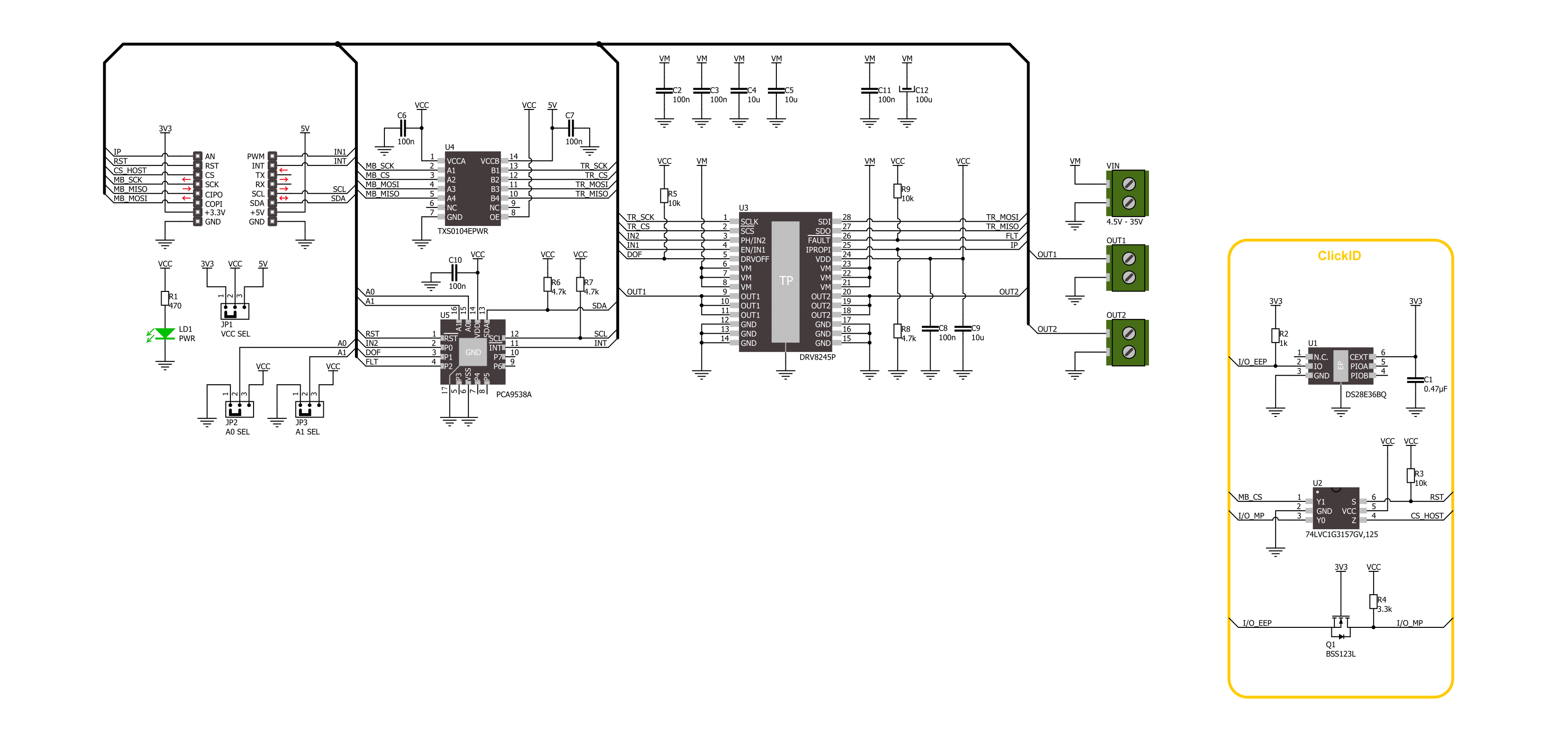
DC Motor 29 Click is based on the DRV8245P, an automotive H-Bridge driver with integrated current sense and diagnostic from Texas Instruments. The driver operates from 4.5V up to 35V and supports a wide range of output load currents for various motors and loads. It integrates an N-channel H-bridge, charge pump regulator, high-side current sensing with regulation, current proportional output, and protection circuitry. The H-bridge output power stage can be operated in different control modes, which allows you to drive a single bidirectional brushed DC motor or two unidirectional brushed DC motors over screw terminals. The driver offers voltage monitoring, load diagnostics, and protection features against overcurrent and overtemperature.
DC Motor 29 Click uses a standard 4-wire SPI serial interface to communicate with the host MCU. The TXS0104, a 4-bit bidirectional voltage-level translator from Texas Instruments, does the logic-level translation. The driver load current analog feedback is available over the IP pin. The controller input 1 for bridge operation is available over the IN1 pin. The PCA9538, an 8-bit I/O port from NXP, provides additional functionalities from the motor driver to the host MCU and can be reset over the RST pin. It provides an input of the controller input 2 for bridge operation. These two controller inputs allow you to use different control schemes. The mode scheme can be changed anytime over the software. The I/O port also allows you to disable
the motor driver. The fault conditions are also monitored over this IC. If a fault condition occurs, the host MCU will be asserted over the FLT pin. The I2C address of the I/O port can be selected over the ADDR SEL jumpers. This Click board™ can operate with either 3.3V or 5V logic voltage levels selected via the VCC SEL jumper. This way, both 3.3V and 5V capable MCUs can use the communication lines properly. Also, this Click board™ comes equipped with a library containing easy-to-use functions and an example code that can be used as a reference for further development.

Features overview
Development board
UNI-DS v8 is a development board specially designed for the needs of rapid development of embedded applications. It supports a wide range of microcontrollers, such as different STM32, Kinetis, TIVA, CEC, MSP, PIC, dsPIC, PIC32, and AVR MCUs regardless of their number of pins, and a broad set of unique functions, such as the first-ever embedded debugger/programmer over WiFi. The development board is well organized and designed so that the end-user has all the necessary elements, such as switches, buttons, indicators, connectors, and others, in one place. Thanks to innovative manufacturing technology, UNI-DS v8 provides a fluid and immersive working experience, allowing access anywhere and under any
circumstances at any time. Each part of the UNI-DS v8 development board contains the components necessary for the most efficient operation of the same board. An advanced integrated CODEGRIP programmer/debugger module offers many valuable programming/debugging options, including support for JTAG, SWD, and SWO Trace (Single Wire Output)), and seamless integration with the Mikroe software environment. Besides, it also includes a clean and regulated power supply module for the development board. It can use a wide range of external power sources, including a battery, an external 12V power supply, and a power source via the USB Type-C (USB-C) connector. Communication options such as USB-UART, USB
HOST/DEVICE, CAN (on the MCU card, if supported), and Ethernet is also included. In addition, it also has the well-established mikroBUS™ standard, a standardized socket for the MCU card (SiBRAIN standard), and two display options for the TFT board line of products and character-based LCD. UNI-DS v8 is an integral part of the Mikroe ecosystem for rapid development. Natively supported by Mikroe software tools, it covers many aspects of prototyping and development thanks to a considerable number of different Click boards™ (over a thousand boards), the number of which is growing every day.

Microcontroller Overview
MCU Card / MCU
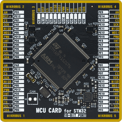
Type
8th Generation
Architecture
ARM Cortex-M4
MCU Memory (KB)
1024
Silicon Vendor
STMicroelectronics
Pin count
144
RAM (Bytes)
196608
You complete me!
Accessories
DC Gear Motor - 430RPM (3-6V) represents an all-in-one combination of a motor and gearbox, where the addition of gear leads to a reduction of motor speed while increasing the torque output. This gear motor has a spur gearbox, making it a highly reliable solution for applications with lower torque and speed requirements. The most critical parameters for gear motors are speed, torque, and efficiency, which are, in this case, 520RPM with no load and 430RPM at maximum efficiency, alongside a current of 60mA and a torque of 50g.cm. Rated for a 3-6V operational voltage range and clockwise/counterclockwise rotation direction, this motor represents an excellent solution for many functions initially performed by brushed DC motors in robotics, medical equipment, electric door locks, and much more.

Used MCU Pins
mikroBUS™ mapper
Take a closer look
Click board™ Schematic
Step by step
Project assembly

Start by selecting your development board and Click board™. Begin with the UNI-DS v8 as your development board.


Software Support
Library Description
This library contains API for DC Motor 29 Click driver.
Key functions:
dcmotor29_register_write- DC Motor 29 data register writing function.dcmotor29_port_expander_read- DC Motor 29 port ecpander read register function.dcmotor29_drive_motor- DC Motor 29 drive motor function.
Open Source
Code example
The complete application code and a ready-to-use project are available through the NECTO Studio Package Manager for direct installation in the NECTO Studio. The application code can also be found on the MIKROE GitHub account.
/*!
 * @file main.c
 * @brief DC Motor 29 Click example
 *
 * # Description
 * This example demonstrates the use of the DC Motor 29 Click board by driving the
 * motor in both directions with braking and coasting in between.
 *
 * The demo application is composed of two sections :
 *
 * ## Application Init
 * Initializes the driver and performs the Click default configuration.
 *
 * ## Application Task
 * Drives the motor in both directions with coasting and braking in between, every sate is lasting 5 seconds.
 *
 * @author Stefan Ilic
 *
 */

#include "board.h"
#include "log.h"
#include "dcmotor29.h"

static dcmotor29_t dcmotor29;
static log_t logger;

void application_init ( void )
{
    log_cfg_t log_cfg;  /**< Logger config object. */
    dcmotor29_cfg_t dcmotor29_cfg;  /**< Click config object. */

    /**
     * Logger initialization.
     * Default baud rate: 115200
     * Default log level: LOG_LEVEL_DEBUG
     * @note If USB_UART_RX and USB_UART_TX
     * are defined as HAL_PIN_NC, you will
     * need to define them manually for log to work.
     * See @b LOG_MAP_USB_UART macro definition for detailed explanation.
     */
    LOG_MAP_USB_UART( log_cfg );
    log_init( &logger, &log_cfg );
    log_info( &logger, " Application Init " );

    // Click initialization.
    dcmotor29_cfg_setup( &dcmotor29_cfg );
    DCMOTOR29_MAP_MIKROBUS( dcmotor29_cfg, MIKROBUS_1 );
    if ( SPI_MASTER_ERROR == dcmotor29_init( &dcmotor29, &dcmotor29_cfg ) )
    {
        log_error( &logger, " Communication init." );
        for ( ; ; );
    }

    if ( DCMOTOR29_ERROR == dcmotor29_default_cfg ( &dcmotor29 ) )
    {
        log_error( &logger, " Default configuration." );
        for ( ; ; );
    }

    log_info( &logger, " Application Task " );
}

void application_task ( void )
{
    dcmotor29_drive_motor( &dcmotor29, DCMOTOR29_DRIVE_MOTOR_CW );
    log_printf( &logger, " Driving motor Clockwise \r\n" );
    Delay_ms ( 1000 );
    Delay_ms ( 1000 );
    Delay_ms ( 1000 );
    Delay_ms ( 1000 );
    Delay_ms ( 1000 );

    dcmotor29_drive_motor( &dcmotor29, DCMOTOR29_DRIVE_MOTOR_BRAKE );
    log_printf( &logger, " Brake is on \r\n" );
    Delay_ms ( 1000 );
    Delay_ms ( 1000 );
    Delay_ms ( 1000 );
    Delay_ms ( 1000 );
    Delay_ms ( 1000 );

    dcmotor29_drive_motor( &dcmotor29, DCMOTOR29_DRIVE_MOTOR_CCW );
    log_printf( &logger, " Driving motor counter-clockwise \r\n" );
    Delay_ms ( 1000 );
    Delay_ms ( 1000 );
    Delay_ms ( 1000 );
    Delay_ms ( 1000 );
    Delay_ms ( 1000 );

    dcmotor29_drive_motor( &dcmotor29, DCMOTOR29_DRIVE_MOTOR_COASTING );
    log_printf( &logger, " Driving motor Coasting \r\n" );
    Delay_ms ( 1000 );
    Delay_ms ( 1000 );
    Delay_ms ( 1000 );
    Delay_ms ( 1000 );
    Delay_ms ( 1000 );
}

int main ( void )
{
    /* Do not remove this line or clock might not be set correctly. */
    #ifdef PREINIT_SUPPORTED
    preinit();
    #endif

    application_init( );

    for ( ; ; )
    {
        application_task( );
    }

    return 0;
}

// ------------------------------------------------------------------------ END


