Create, command, and innovate like never before with eINK display and STM32L496AG
MCU and eINK – A perfect symbiosis
Published Jul 22, 2025
Click board™
eINK Click
Dev. board
Discovery kit with STM32L496AG MCU
Compiler
NECTO Studio
MCU
STM32L496AG
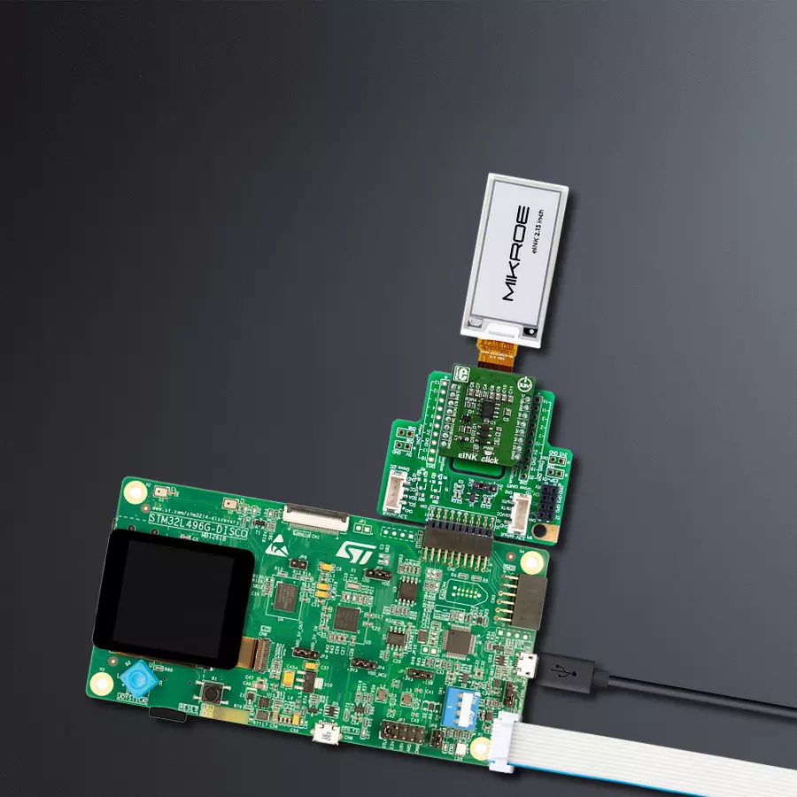
Our adapter solution establishes a perfect symbiosis between the MCU and eINK displays, allowing for smooth, intuitive control and a world of possibilities
A
A
Hardware Overview
How does it work?
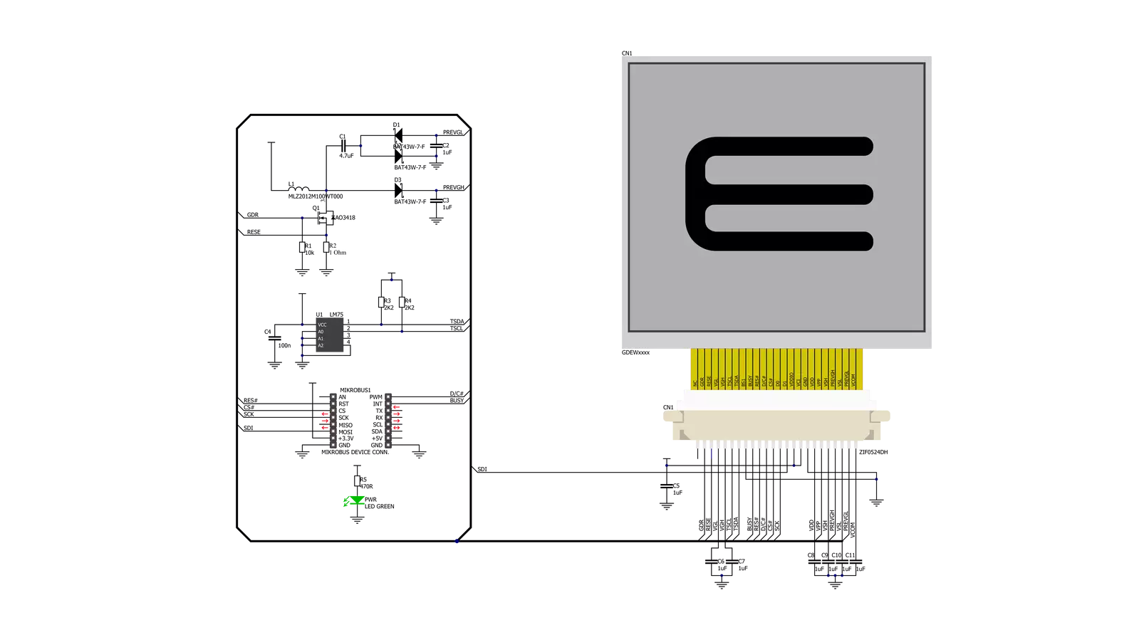
eINK Click is an adapter Click board™, used to interface a compatible eINK display with the host MCU. The most distinctive feature of the eINK displays is their very low power consumption and the ability to retain the information, even after disconnecting from the power source. The power is consumed only when the display content is changing. The Click board™ comes shipped with the 172x72 eINK display, driven by the integrated SSD1606 controller and it can display 4 shades: black, dark gray, light gray and white. The same type of display is used on the popular Kindle E-readers. The eINK is a reasonably new technology with a promising future. The displayed content does not degrade when exposed to direct sunlight, the display actually behaves like a real paper; it is more readable when there is more light hitting its surface. There is a wide range of applications, where eINK can be implemented: it can be used for very low power consumption applications that require display output, such as mobile phones and wearables, industrial and packaging applications, electronic reading and writing, electronic shelf labels and similar
applications that can utilize this type of display. The working principle of the eINK display is rather simple: there are black and white pigments trapped inside the microcapsules, which are dispersed in a clear fluid between two electrodes. The white pigments are positively charged, while the black pigments are negatively charged. When the electromagnetic field is formed between the electrodes, the pigments get repelled or attracted to the electrodes, depending on the field orientation. This results in bright or dark pigments being positioned towards the bottom or top surface of the microcapsule. When the black pigments are positioned on the top surface of the microcapsule, it is observed as the black pixel, and vice versa. It is also possible to position the pigment charges so that each color occupies one half of the microcapsule top surface and that is how gray shades are produced. The display included with the eINK click is the EA-EPA20-A, a 2 inch,172x72 pixels ePAPER display with the integrated SSD1606 driver/controller, from Electronic Assembly. This display uses the SPI communication protocol for the communication
with the host MCU. This display features inherently wide viewing angle and high contrast, as well as good readability in daylight conditions. The click board™ itself carries the supporting electronics, used to provide all the necessary voltages for the proper operation of the EPA20-A display. The SSD1606 pins are routed through the flat cable of the display and connected via the 24pin, 0.5mm ZIF connector on the click board. From there, the command and data lines are routed to the appropriate pins on the mikroBUS™ of the eINK click. The eINK click also contains the LM75 thermal sensor, which uses I2C protocol to communicate with the SSD1606 driver IC. This is required for thermal compensation of the display, so it can be operated in a wide temperature range, from 0°C to +50°C. The total power consumption of this device is very low. The power is only required when rearranging of the microcell pigments is required, while no power is required to sustain the content of the display. The display retains the content, even when the power is disconnected. The click board and the display are powered via the 3.3V rail of the mikroBUS™.

Features overview
Development board
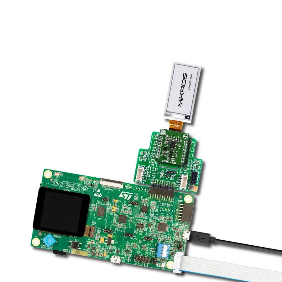
The 32L496GDISCOVERY Discovery kit serves as a comprehensive demonstration and development platform for the STM32L496AG microcontroller, featuring an Arm® Cortex®-M4 core. Designed for applications that demand a balance of high performance, advanced graphics, and ultra-low power consumption, this kit enables seamless prototyping for a wide range of embedded solutions. With its innovative energy-efficient
architecture, the STM32L496AG integrates extended RAM and the Chrom-ART Accelerator, enhancing graphics performance while maintaining low power consumption. This makes the kit particularly well-suited for applications involving audio processing, graphical user interfaces, and real-time data acquisition, where energy efficiency is a key requirement. For ease of development, the board includes an onboard ST-LINK/V2-1
debugger/programmer, providing a seamless out-of-the-box experience for loading, debugging, and testing applications without requiring additional hardware. The combination of low power features, enhanced memory capabilities, and built-in debugging tools makes the 32L496GDISCOVERY kit an ideal choice for prototyping advanced embedded systems with state-of-the-art energy efficiency.

Microcontroller Overview
MCU Card / MCU

Architecture
ARM Cortex-M4
MCU Memory (KB)
1024
Silicon Vendor
STMicroelectronics
Pin count
169
RAM (Bytes)
327680
You complete me!
Accessories
The E-Paper 2.13" display is based on Active Matrix Electrophoretic Display (AMEPD) technology and has an integrated pixel driver, which uses the SPI interface to communicate with the host MCU. The display has a 24-pin flat-printed cable that connects to the host controller. A perfect solution for easy connection is offered in the form of a Click board™. The E-Paper 2.13" display has a resolution of 122(V) X 250(H) pixels and an active display area of 23.71 X 48.55. The size of its square-shaped pixels is 0.194mm x 0.194mm. Thanks to the AMEPD technology, the screen displays clear and crisp graphics and has an ultra-wide viewing range. Another key feature of the E-Ink technology is the extremely low power consumption, even when the display actively refreshes its content.

Used MCU Pins
mikroBUS™ mapper
Take a closer look
Click board™ Schematic
Step by step
Project assembly

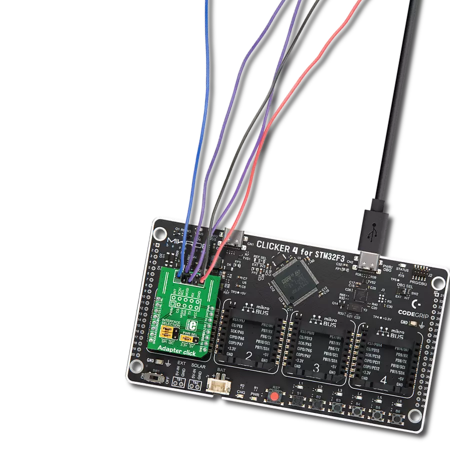
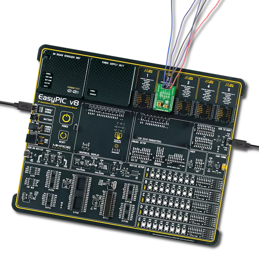
Start by selecting your development board and Click board™. Begin with the Discovery kit with STM32L496AG MCU as your development board.


Track your results in real time
Application Output
1. Application Output - In Debug mode, the 'Application Output' window enables real-time data monitoring, offering direct insight into execution results. Ensure proper data display by configuring the environment correctly using the provided tutorial.

2. UART Terminal - Use the UART Terminal to monitor data transmission via a USB to UART converter, allowing direct communication between the Click board™ and your development system. Configure the baud rate and other serial settings according to your project's requirements to ensure proper functionality. For step-by-step setup instructions, refer to the provided tutorial.

3. Plot Output - The Plot feature offers a powerful way to visualize real-time sensor data, enabling trend analysis, debugging, and comparison of multiple data points. To set it up correctly, follow the provided tutorial, which includes a step-by-step example of using the Plot feature to display Click board™ readings. To use the Plot feature in your code, use the function: plot(*insert_graph_name*, variable_name);. This is a general format, and it is up to the user to replace 'insert_graph_name' with the actual graph name and 'variable_name' with the parameter to be displayed.

Software Support
Library Description
This library contains API for eINK Click driver.
Key functions:
eink200_set_lut- Set LUT tableeink200_display_image- Displays imageeink200_set_font- Set text font
Open Source
Code example
The complete application code and a ready-to-use project are available through the NECTO Studio Package Manager for direct installation in the NECTO Studio. The application code can also be found on the MIKROE GitHub account.
/*!
 * \file
 * \brief Eink Click example
 *
 * # Description
 * This application demonstrates the use of eINK Click board.
 *
 * The demo application is composed of two sections :
 *
 * ## Application Init
 * Initializes the driver and configures the Click board for 2.00 inch eINK display.
 * After that, if the TEXT mode is supported, shows a desired text messages on the display.
 *
 * ## Application Task
 * Draws two demo images to the display with a one-second delay between each drawing.
 *
 * @note
 * Due to insuficient RAM memory, only the IMAGE mode is supported with 8-bit PIC microcontrollers.
 *
 * Here is the procedure for creating an Image or Font arrays:
 *
 * - Create Image:
 *    Save the image in resolution of 172x72 px with the extension (jpg) ...
 *    Upload the image to Image2Lcd program
 *    Set parameters to:
 *           1. Output file type : C array
 *           2. Scan Mode : Vertical scan
 *           3. Bits Pixel : 4 Color
 *           4. Max Width and Height : 172x72
 *           5. Select only MSB first checkmark
 *           6. Check Reverse color and adjust Normal type
 *    The image to be generated should contain exact 3096 bytes ...
 *    Insert the image into the file eink_display_image.h
 *
 * - Create Font:
 *    Create a new VisualTFT project
 *    Add label and adjust text font
 *    Generate source code
 *    Copy the font array from resource.c file and paste it to eink200inch_font.h file
 *
 * *** Changing the LUT table can lead to loss of display performance ....
 *
 * \author MikroE Team
 *
 */
// ------------------------------------------------------------------- INCLUDES

#include "board.h"
#include "log.h"
#include "eink.h"
#include "eink200inch_image.h"
#ifndef IMAGE_MODE_ONLY
#include "eink200inch_font.h"
#endif

// ------------------------------------------------------------------ VARIABLES

static eink_t eink;

const uint8_t eink_lut_table[ 90 ] =
{
    0x82, 0x00, 0x00, 0x00, 0xAA, 0x00, 0x00, 0x00,
    0xAA, 0xAA, 0x00, 0x00, 0xAA, 0xAA, 0xAA, 0x00,
    0x55, 0xAA, 0xAA, 0x00, 0x55, 0x55, 0x55, 0x55,
    0xAA, 0xAA, 0xAA, 0xAA, 0x55, 0x55, 0x55, 0x55,
    0xAA, 0xAA, 0xAA, 0xAA, 0x15, 0x15, 0x15, 0x15,
    0x05, 0x05, 0x05, 0x05, 0x01, 0x01, 0x01, 0x01,
    0x00, 0x00, 0x00, 0x00, 0x00, 0x00, 0x00, 0x00,
    0x00, 0x00, 0x00, 0x00, 0x00, 0x00, 0x00, 0x00,
    0x00, 0x00, 0x00, 0x00, 0x00, 0x00, 0x00, 0x00,
    0x00, 0x00, 0x00, 0x00, 0x00, 0x00, 0x00, 0x00,
    0x41, 0x45, 0xF1, 0xFF, 0x5F, 0x55, 0x01, 0x00,
    0x00, 0x00

};

uint8_t demo_text[ 5 ] = { 'e', 'I', 'N', 'K' , 0 };
uint8_t demo_text1[ 8 ] = { 'D', 'i', 's', 'p', 'l', 'a', 'y', 0 };
uint8_t demo_text2[ 10 ] = { '2', '.', '0', '0', 'i', 'n', 'c', 'h', 0 };

// ------------------------------------------------------ APPLICATION FUNCTIONS

void application_init ( void )
{
    eink_cfg_t cfg;
    eink200inch_font_t cfg_font;
    eink_text_set_t text_set;

    //  Click initialization.
    eink_cfg_setup( &cfg );
    EINK_MAP_MIKROBUS( cfg, MIKROBUS_1 );
    eink_init( &eink, &cfg );

    eink_start_config( &eink );
    eink_set_lut( &eink, eink_lut_table, 90 );
    Delay_ms ( 1000 );

#ifndef IMAGE_MODE_ONLY
    cfg_font.p_font = &guiFont_Tahoma_10_Regular[ 0 ];
    cfg_font.color = EINK_SCREEN_COLOR_WHITE;
    cfg_font.orientation = EINK_FO_HORIZONTAL;
    eink_set_font( &eink, &cfg_font );

    text_set.n_char = 4;
    text_set.text_x = 10;
    text_set.text_y = 50;
    eink_text( &eink, &demo_text[ 0 ], &text_set );
    text_set.n_char = 7;
    text_set.text_x = 10;
    text_set.text_y = 90;
    eink_text( &eink, &demo_text1[ 0 ], &text_set );
    text_set.n_char = 8;
    text_set.text_x = 10;
    text_set.text_y = 130;
    eink_text( &eink, &demo_text2[ 0 ], &text_set );
    Delay_ms ( 1000 );
    Delay_ms ( 1000 );
    Delay_ms ( 1000 );
    Delay_ms ( 1000 );
    Delay_ms ( 1000 );
#endif
}

void application_task ( void )
{
    eink_display_image ( &eink, demo_image_black );
    Delay_1sec( );
    eink_display_image ( &eink, demo_image_white );
    Delay_1sec( );
}

int main ( void )
{
    /* Do not remove this line or clock might not be set correctly. */
    #ifdef PREINIT_SUPPORTED
    preinit();
    #endif

    application_init( );

    for ( ; ; )
    {
        application_task( );
    }

    return 0;
}

// ------------------------------------------------------------------------ END
Additional Support
Resources
Category:Adapter