Revolutionize automation and control with EKMC1606112 and TM4C1294NCZAD
Detect the unseen: Pyroelectric wonders await!

Published Oct 07, 2023
Click board™
Motion 3 Click
Dev. board
Fusion for Tiva v8
Compiler
NECTO Studio
MCU
TM4C1294NCZAD
We are dedicated to simplifying your life and reducing energy wastage through our PIR motion sensor solutions, ensuring that your environments respond intelligently to human activity, leading to a more sustainable and comfortable future
A
A
Hardware Overview
How does it work?
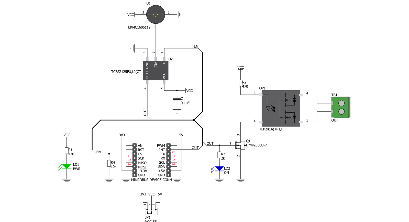
Motion 3 Click is based on EKMC1606112, a PIR motion sensor from Panasonic used as a human motion detector. This PIR sensor can detect changes in the amount of infrared radiation impinging upon it, which varies depending on the temperature and surface characteristics of the objects in front of the sensor. Detection performance of EKMC1606112 at ambient temperature of 25℃ with temperature difference of 8℃ is up to 17m and for temperature difference of 4℃ it's up to 12m. Angle detection area with 128 detection zones is 62°(±31°)horizontal and 62°(±31°)vertical. Output from PIR sensor is feed into buffer and then photorelay alowing users to directly control with galvanic isolation from sensor and MCU electronic devices such as lights, motors,
gates, and more. The TLP241A photorelay is able to effectively replace traditionally used mechanical relays, bringing up the full set of inherited benefits: virtually unlimited number of cycles since there are no moving parts that would wear off, no bouncing effect on the output contacts, high resistance to mechanical shock and environmental influence, low current required for the activation, constant resistance since no carbon and rust can build up on contacts, there is no sparking or electric arc forming while operated, compact size, higher isolation voltage, and so on. When an object, such as a person, passes in front of the background, such as a wall, the temperature at that point in the sensor's field of view will rise from room temperature to body temperature, and
then back again. The sensor converts the resulting change in the incoming infrared radiation into a change in the output voltage, and this triggers the detection. Objects of similar temperature but different surface characteristics may also have a different infrared emission pattern, and thus moving them with respect to the background may trigger the detector as well. In some cases, going back and forth towards the sensor (parallel movement to the axis Z), may not be detected. Difficulty in sensing the heat source is that glass, acrylic or similar materials standing between the target and the sensor may not allow a correct transmission of infrared rays and also non-movement or quick movements of the heat source inside the detection area.


Features overview
Development board
Fusion for TIVA v8 is a development board specially designed for the needs of rapid development of embedded applications. It supports a wide range of microcontrollers, such as different 32-bit ARM® Cortex®-M based MCUs from Texas Instruments, regardless of their number of pins, and a broad set of unique functions, such as the first-ever embedded debugger/programmer over a WiFi network. The development board is well organized and designed so that the end-user has all the necessary elements, such as switches, buttons, indicators, connectors, and others, in one place. Thanks to innovative manufacturing technology, Fusion for TIVA v8 provides a fluid and immersive working experience, allowing access
anywhere and under any circumstances at any time. Each part of the Fusion for TIVA v8 development board contains the components necessary for the most efficient operation of the same board. An advanced integrated CODEGRIP programmer/debugger module offers many valuable programming/debugging options, including support for JTAG, SWD, and SWO Trace (Single Wire Output)), and seamless integration with the Mikroe software environment. Besides, it also includes a clean and regulated power supply module for the development board. It can use a wide range of external power sources, including a battery, an external 12V power supply, and a power source via the USB Type-C (USB-C) connector.
Communication options such as USB-UART, USB HOST/DEVICE, CAN (on the MCU card, if supported), and Ethernet is also included. In addition, it also has the well-established mikroBUS™ standard, a standardized socket for the MCU card (SiBRAIN standard), and two display options for the TFT board line of products and character-based LCD. Fusion for TIVA v8 is an integral part of the Mikroe ecosystem for rapid development. Natively supported by Mikroe software tools, it covers many aspects of prototyping and development thanks to a considerable number of different Click boards™ (over a thousand boards), the number of which is growing every day.

Microcontroller Overview
MCU Card / MCU
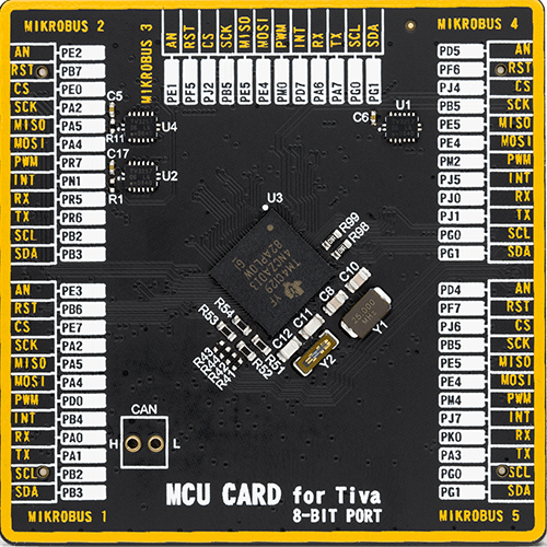
Type
8th Generation
Architecture
ARM Cortex-M4
MCU Memory (KB)
1024
Silicon Vendor
Texas Instruments
Pin count
212
RAM (Bytes)
262144
Used MCU Pins
mikroBUS™ mapper
Take a closer look
Click board™ Schematic
Step by step
Project assembly

Start by selecting your development board and Click board™. Begin with the Fusion for Tiva v8 as your development board.


Software Support
Library Description
This library contains API for Motion 3 Click driver.
Key functions:
motion3_enable- This function enables/disables motion sensor by setting EN pin statemotion3_detect_state- This function returns INT pin state
Open Source
Code example
The complete application code and a ready-to-use project are available through the NECTO Studio Package Manager for direct installation in the NECTO Studio. The application code can also be found on the MIKROE GitHub account.
/*!
 * @file main.c
 * @brief Motion 3 Click Example.
 *
 * # Description
 * This example demonstrates the use of Motion 3 Click boards.
 *
 * The demo application is composed of two sections :
 *
 * ## Application Init
 * Initializes the driver and enables the motion sensor.
 *
 * ## Application Task
 * It checks if the sensor has detected movement and therefore displays
 * the desired message on the USB UART.
 *
 * @author Jelena Milosavljevic
 *
 */
// ------------------------------------------------------------------- INCLUDES

#include "board.h"
#include "log.h"
#include "motion3.h"

// ------------------------------------------------------------------ VARIABLES

static motion3_t motion3;   /**< Motion 3 Click driver object. */
static log_t logger;    /**< Logger object. */

motion3_detect_state_t motion_state;
motion3_detect_state_t motion_old_state;
// ------------------------------------------------------ APPLICATION FUNCTIONS

void application_init ( void ) {
    log_cfg_t log_cfg;  /**< Logger config object. */
    motion3_cfg_t motion3_cfg;  /**< Click config object. */

    /**
     * Logger initialization.
     * Default baud rate: 115200
     * Default log level: LOG_LEVEL_DEBUG
     * @note If USB_UART_RX and USB_UART_TX
     * are defined as HAL_PIN_NC, you will
     * need to define them manually for log to work.
     * See @b LOG_MAP_USB_UART macro definition for detailed explanation.
     */
    LOG_MAP_USB_UART( log_cfg );
    log_init( &logger, &log_cfg );
    log_info( &logger, " Application Init " );

    // Click initialization.

    motion3_cfg_setup( &motion3_cfg );
    MOTION3_MAP_MIKROBUS( motion3_cfg, MIKROBUS_5 );
    if ( motion3_init( &motion3, &motion3_cfg ) == DIGITAL_OUT_UNSUPPORTED_PIN ) {

        log_error( &logger, " Application Init Error. " );
        log_info( &logger, " Please, run program again... " );

        for ( ; ; );
    }

    motion3_enable( &motion3, MOTION3_MODULE_ENABLE );
    Delay_ms ( 100 );
    log_printf( &logger, "The sensor is ready.\r\n" );
    log_printf( &logger, "-----------------------\r\n" );
}

void application_task ( void ) {
    uint8_t int_status;

    int_status = motion3_detect_state( &motion3 );

    if ( int_status == MOTION3_DETECT_OBJECT )
    {
        log_printf( &logger, "Motion detected!\r\n" );
        log_printf( &logger, "-----------------------\r\n" );
        while ( int_status == MOTION3_DETECT_OBJECT ) {

            int_status = motion3_detect_state( &motion3 );
        }
        log_printf( &logger, "The sensor is ready.\r\n" );
        log_printf( &logger, "-----------------------\r\n" );
        Delay_ms ( 100 );
    }
}

int main ( void )
{
    /* Do not remove this line or clock might not be set correctly. */
    #ifdef PREINIT_SUPPORTED
    preinit();
    #endif

    application_init( );

    for ( ; ; )
    {
        application_task( );
    }

    return 0;
}

// ------------------------------------------------------------------------ END
Additional Support
Resources
Category:Motion


