Elevate your equipment's comfort with EMC2103 and STM32L496AG
Quietly efficient, delightfully cool

Published Jul 22, 2025
Click board™
Fan 6 Click
Dev. board
Discovery kit with STM32L496AG MCU
Compiler
NECTO Studio
MCU
STM32L496AG
Take charge of your comfort with our fan speed management system, allowing you to adjust fan speeds for a personalized cooling experience easily
A
A
Hardware Overview
How does it work?
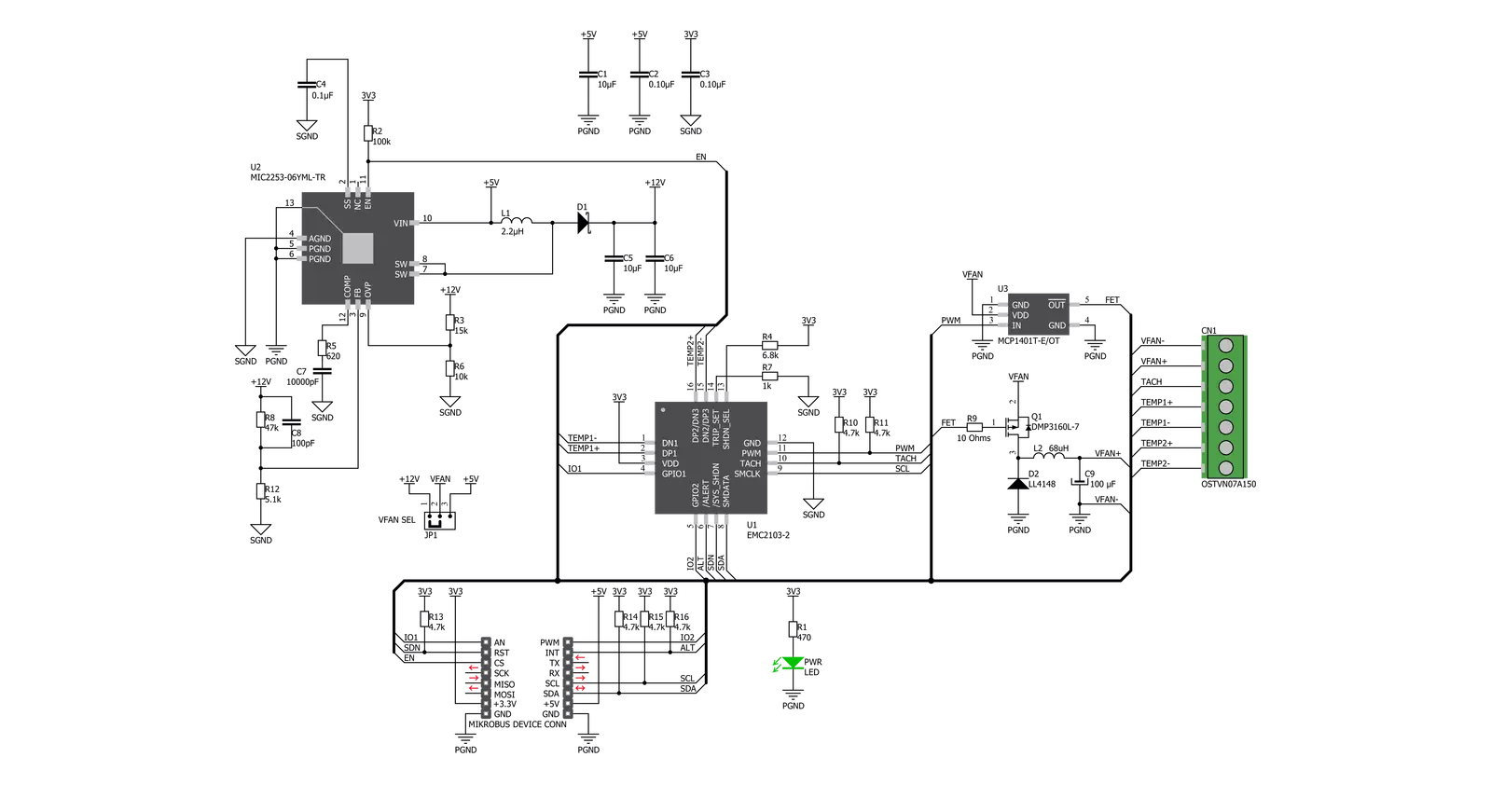
Fan 6 Click is based on the EMC2103, an SMBus-compliant fan controller with up to 3 external and one internal temperature channel from Microchip. It allows the user to program temperatures generated from external sources to control the fan speed. This functionality also supports DTS data from the CPU. By pushing DTS or standard temperature values into dedicated registers, the external temperature readings can be used with the external diode(s) and internal diode to control the fan speed. The EMC2103 from Microchip also includes a hardware programmable temperature limit and dedicated system shutdown output for thermal protection of critical circuitry. The EMC2103 supports a high or low-frequency PWM driver. The output can be configured as either push-pull or open drain, and the frequency ranges from 9.5Hz to 26kHz in four programmable frequency bands. The EMC2103 includes an RPM-based Fan Speed Control Algorithm. This fan control algorithm uses Proportional, Integral, and Derivative terms to automatically approach and
maintain the system's desired fan speed to an accuracy directly proportional to the accuracy of the clock source. The EMC2103 supports DTS (Intel's Digital Temperature Sensor) data in the Fan Control Look-Up Table. Intel's DTS data is a positive number representing the processor's relative temperature below a fixed value called TCONTROL, which generally equals 100°C for Intel Mobile processors. For example, a DTS value of 10°C means the actual processor temperature is 10°C below TCONTROL or equal to 90°C. The EMC2103's RPM-based Fan Speed Control Algorithm has programmable configuration settings for parameters such as ramp-rate control and spin-up conditions. The fan driver automatically detects and attempts to alleviate a stalled/stuck fan condition while also asserting the ALR pin. The tachometer measurement circuitry is used in conjunction with the RPM-based Fan Speed Control Algorithm to update the fan driver output. Additionally, it can be used in Direct Setting mode as a diagnostic for host-based fan
control. This method monitors the TACH signal in real-time. It constantly updates the tachometer measurement by reporting the number of clocks between a user's programmed number of edges on the TACH signal. The External Diode 1 channel can support a diode-connected transistor (such as a 2N3904) or a substrate transistor requiring the BJT or transistor model (such as those found in a CPU or GPU). The External Diode 2 channel supports any diode connection or can be configured to operate in an anti-parallel diode (APD) mode. The MIC2253 is a constant frequency, pulse-width modulated (PWM) peak current-mode step-up regulator. A reference voltage is fed into the PWM engine, where the duty cycle output of the constant frequency PWM engine is computed from the error, or difference, between the REF and FB voltages. The PWM engine encompasses the circuit blocks to implement a current-mode boost switching power supply, allowing Fan 6 click to drive a 12V fan.

Features overview
Development board
The 32L496GDISCOVERY Discovery kit serves as a comprehensive demonstration and development platform for the STM32L496AG microcontroller, featuring an Arm® Cortex®-M4 core. Designed for applications that demand a balance of high performance, advanced graphics, and ultra-low power consumption, this kit enables seamless prototyping for a wide range of embedded solutions. With its innovative energy-efficient
architecture, the STM32L496AG integrates extended RAM and the Chrom-ART Accelerator, enhancing graphics performance while maintaining low power consumption. This makes the kit particularly well-suited for applications involving audio processing, graphical user interfaces, and real-time data acquisition, where energy efficiency is a key requirement. For ease of development, the board includes an onboard ST-LINK/V2-1
debugger/programmer, providing a seamless out-of-the-box experience for loading, debugging, and testing applications without requiring additional hardware. The combination of low power features, enhanced memory capabilities, and built-in debugging tools makes the 32L496GDISCOVERY kit an ideal choice for prototyping advanced embedded systems with state-of-the-art energy efficiency.

Microcontroller Overview
MCU Card / MCU

Architecture
ARM Cortex-M4
MCU Memory (KB)
1024
Silicon Vendor
STMicroelectronics
Pin count
169
RAM (Bytes)
327680
Used MCU Pins
mikroBUS™ mapper
Take a closer look
Click board™ Schematic
Step by step
Project assembly

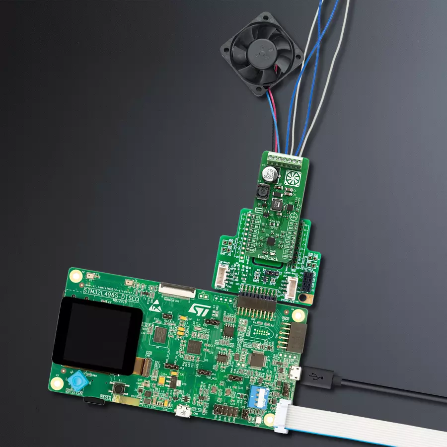
Start by selecting your development board and Click board™. Begin with the Discovery kit with STM32L496AG MCU as your development board.


Track your results in real time
Application Output
1. Application Output - In Debug mode, the 'Application Output' window enables real-time data monitoring, offering direct insight into execution results. Ensure proper data display by configuring the environment correctly using the provided tutorial.

2. UART Terminal - Use the UART Terminal to monitor data transmission via a USB to UART converter, allowing direct communication between the Click board™ and your development system. Configure the baud rate and other serial settings according to your project's requirements to ensure proper functionality. For step-by-step setup instructions, refer to the provided tutorial.

3. Plot Output - The Plot feature offers a powerful way to visualize real-time sensor data, enabling trend analysis, debugging, and comparison of multiple data points. To set it up correctly, follow the provided tutorial, which includes a step-by-step example of using the Plot feature to display Click board™ readings. To use the Plot feature in your code, use the function: plot(*insert_graph_name*, variable_name);. This is a general format, and it is up to the user to replace 'insert_graph_name' with the actual graph name and 'variable_name' with the parameter to be displayed.

Software Support
Library Description
This library contains API for Fan 6 Click driver.
Key functions:
fan6_read_eeprom- This function reads 256 bytes from EEPROMfan6_set_pwm_mode- This function sets Fan on PWM mode and determines Fan speed (PWM duty)fan6_read_tachometer- This function reads current tachometer value and calculates that value in rpm
Open Source
Code example
The complete application code and a ready-to-use project are available through the NECTO Studio Package Manager for direct installation in the NECTO Studio. The application code can also be found on the MIKROE GitHub account.
/*!
 * \file
 * \brief Fan6 Click example
 *
 * # Description
 * This demo application reads tachometer value which is calculated as rpm value, and reads
 * temperature of external diode in celsius value.
 *
 * The demo application is composed of two sections :
 *
 * ## Application Init
 * Initializes device configuration.
 *
 * ## Application Task
 * Reads tachometer value which is calculated as rpm value, and reads
 * temperature of external diode in celsius value. All this results logs on USB UART. Repeats operation
 * every 500 ms.
 *
 * \author MikroE Team
 *
 */
// ------------------------------------------------------------------- INCLUDES

#include "board.h"
#include "log.h"
#include "fan6.h"

// ------------------------------------------------------------------ VARIABLES

static fan6_t fan6;
static log_t logger;

static uint32_t tachometer;
static uint8_t duty_cycle = 0;

// ------------------------------------------------------ APPLICATION FUNCTIONS

void application_init ( void )
{
    log_cfg_t log_cfg;
    fan6_cfg_t cfg;

    /**
     * Logger initialization.
     * Default baud rate: 115200
     * Default log level: LOG_LEVEL_DEBUG
     * @note If USB_UART_RX and USB_UART_TX
     * are defined as HAL_PIN_NC, you will
     * need to define them manually for log to work.
     * See @b LOG_MAP_USB_UART macro definition for detailed explanation.
     */
    LOG_MAP_USB_UART( log_cfg );
    log_init( &logger, &log_cfg );
    log_info( &logger, "---- Application Init ----" );

    //  Click initialization.

    fan6_cfg_setup( &cfg );
    FAN6_MAP_MIKROBUS( cfg, MIKROBUS_1 );
    fan6_init( &fan6, &cfg );

    fan6_enable_device( &fan6, 1 );
    Delay_ms ( 500 );

    fan6_default_cfg( &fan6 );
    tachometer = 0;
}

void application_task ( void )
{
    float temp_diode;

    temp_diode = fan6_get_temperature( &fan6, FAN6_INTERNAL_TEMP_READ_REG );
    log_printf( &logger, "Temperature of DIODE is: %f - Cels \r\n", temp_diode );

    fan6_set_pwm_mode( &fan6, duty_cycle );

    duty_cycle += 5;

    tachometer = fan6_read_tachometer( &fan6 );
    log_printf( &logger, "Tachometer value is: %lu rpm \r\n", tachometer );
    log_printf( &logger, "---------------------------------------- \r\n", tachometer );

    Delay_ms ( 500 );
}

int main ( void )
{
    /* Do not remove this line or clock might not be set correctly. */
    #ifdef PREINIT_SUPPORTED
    preinit();
    #endif

    application_init( );

    for ( ; ; )
    {
        application_task( );
    }

    return 0;
}

// ------------------------------------------------------------------------ END
Additional Support
Resources
Category:Brushless


