Revolutionize the way you track movement with FXOS8700CQ and STM32F405RG
Your path to seamless motion tracking

Published Sep 12, 2023
Click board™
6DOF IMU 3 Click
Dev. board
UNI-DS v8
Compiler
NECTO Studio
MCU
STM32F405RG
Our 6DOF IMU solution empowers you to achieve precise motion and position tracking, opening doors to seamless navigation in various applications
A
A
Hardware Overview
How does it work?
6DOF IMU 3 Click is based on the FXOS8700CQ, a small, low-power, 3-axis, linear accelerometer and 3-axis magnetometer combined into a single package from NXP Semiconductor. The device features a selectable I2C or point-to-point SPI serial interface with a 14-bit accelerometer and 16-bit magnetometer ADC resolution and smart-embedded functions. The FXOS8700CQ has dynamically selectable acceleration full-scale ranges of ±2 g/±4 g/±8 g and a fixed magnetic measurement range of ±1200 μT. For each sensor, the user selects output data rates (ODR) from 1.563Hz to 800Hz. Interleaved magnetic and acceleration data is available at ODR rates up to 400Hz. The sensor's sensitivity is represented in mg/LSB for the accelerometer and μT/LSB for the magnetometer. The magnetometer sensitivity is
fixed at 0.1 μT/LSB. The accelerometer sensitivity changes with the full-scale range selected by the user. Accelerometer sensitivity is 0.244 mg/LSB in 2 g mode, 0.488 mg/LSB in 4 g mode, and 0.976 mg/LSB in 8 g mode, making it ideal for applications such as used for security, like motion detection, door opening, smart home applications, robotics and unmanned aerial vehicles (UAVs) with electronic compass (e-compass) function, in medical purposes, like patient monitoring, fall detection and more. 6DOF IMU 3 Click supports both SPI and I2C communication interfaces, allowing it to be used with various MCUs. The communication interface can be selected by moving SMD jumpers grouped under the COM SEL to an appropriate position (SPI or I2C). The slave I2C address can also be configured by an
SMD jumper when the Click board™ is operated in the I2C mode. An SMD jumper labeled ADDR SEL sets the least significant bit (LSB) of the I2C address. The I2C interface complies with fast mode (400 kHz) and normal mode (100 kHz) I2C standards, while the SPI interface is a classical Host/Peripheral serial port. The FXOS8700CQ is always considered as the peripheral and thus is never initiating the communication. This Click board™ can be operated only with a 3.3V logic voltage level. The board must perform appropriate logic voltage level conversion before using MCUs with different logic levels. Also, it comes equipped with a library containing functions and an example code that can be used as a reference for further development.


Features overview
Development board
UNI-DS v8 is a development board specially designed for the needs of rapid development of embedded applications. It supports a wide range of microcontrollers, such as different STM32, Kinetis, TIVA, CEC, MSP, PIC, dsPIC, PIC32, and AVR MCUs regardless of their number of pins, and a broad set of unique functions, such as the first-ever embedded debugger/programmer over WiFi. The development board is well organized and designed so that the end-user has all the necessary elements, such as switches, buttons, indicators, connectors, and others, in one place. Thanks to innovative manufacturing technology, UNI-DS v8 provides a fluid and immersive working experience, allowing access anywhere and under any
circumstances at any time. Each part of the UNI-DS v8 development board contains the components necessary for the most efficient operation of the same board. An advanced integrated CODEGRIP programmer/debugger module offers many valuable programming/debugging options, including support for JTAG, SWD, and SWO Trace (Single Wire Output)), and seamless integration with the Mikroe software environment. Besides, it also includes a clean and regulated power supply module for the development board. It can use a wide range of external power sources, including a battery, an external 12V power supply, and a power source via the USB Type-C (USB-C) connector. Communication options such as USB-UART, USB
HOST/DEVICE, CAN (on the MCU card, if supported), and Ethernet is also included. In addition, it also has the well-established mikroBUS™ standard, a standardized socket for the MCU card (SiBRAIN standard), and two display options for the TFT board line of products and character-based LCD. UNI-DS v8 is an integral part of the Mikroe ecosystem for rapid development. Natively supported by Mikroe software tools, it covers many aspects of prototyping and development thanks to a considerable number of different Click boards™ (over a thousand boards), the number of which is growing every day.

Microcontroller Overview
MCU Card / MCU
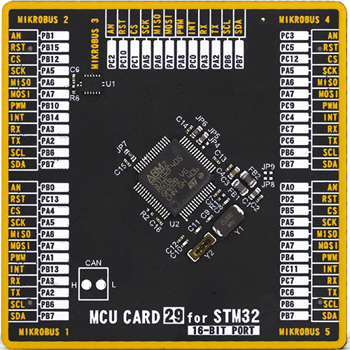
Type
8th Generation
Architecture
ARM Cortex-M4
MCU Memory (KB)
1024
Silicon Vendor
STMicroelectronics
Pin count
64
RAM (Bytes)
196608
Used MCU Pins
mikroBUS™ mapper
Take a closer look
Click board™ Schematic

Step by step
Project assembly

Start by selecting your development board and Click board™. Begin with the UNI-DS v8 as your development board.


Software Support
Library Description
This library contains API for 6DOF IMU 3 Click driver.
Key functions:
c6dofimu3_check_id- Function check device ID by read ID value from the sensor ID register address of FXOS8700CQ 6-axis sensor with integrated linear accelerometer and magnetometer on 6DOF IMU 3 Click board.c6dofimu3_read_mag_data- Function read 16-bit ( signed ) Magnetometer X-axis, Y-axis data and Z-axis data from the 6 targeted starts from C6DOFIMU3_M_OUT_X_MSB register address of FXOS8700CQ 6-axis sensor with integrated linear accelerometer and magnetometer on 6DOF IMU 3 Click board.c6dofimu3_read_accel_data- Function read 14-bit ( signed ) Accel X-axis, Y-axis data and Z-axis data from the 6 targeted starts from C6DOFIMU3_OUT_X_MSB register address of FXOS8700CQ 6-axis sensor with integrated linear accelerometer and magnetometer on 6DOF IMU 3 Click board.
Open Source
Code example
The complete application code and a ready-to-use project are available through the NECTO Studio Package Manager for direct installation in the NECTO Studio. The application code can also be found on the MIKROE GitHub account.
/*!
 * \file
 * \brief 6Dofimu3 Click example
 *
 * # Description
 * This example demonstrates the use of 6DOF IMU 3 Click board.
 *
 * The demo application is composed of two sections :
 *
 * ## Application Init
 * Initializes the driver and sets the device default configuration.
 *
 * ## Application Task
 * Measures acceleration and magnetometer data and displays the results on USB UART each second.
 *
 * \author MikroE Team
 *
 */
// ------------------------------------------------------------------- INCLUDES

#include "board.h"
#include "log.h"
#include "c6dofimu3.h"

// ------------------------------------------------------------------ VARIABLES

static c6dofimu3_t c6dofimu3;
static log_t logger;

c6dofimu3_accel_t accel_data;
c6dofimu3_mag_t mag_data;

// ------------------------------------------------------ APPLICATION FUNCTIONS

void application_init ( void )
{
    log_cfg_t log_cfg;
    c6dofimu3_cfg_t cfg;

    /**
     * Logger initialization.
     * Default baud rate: 115200
     * Default log level: LOG_LEVEL_DEBUG
     * @note If USB_UART_RX and USB_UART_TX
     * are defined as HAL_PIN_NC, you will
     * need to define them manually for log to work.
     * See @b LOG_MAP_USB_UART macro definition for detailed explanation.
     */
    LOG_MAP_USB_UART( log_cfg );
    log_init( &logger, &log_cfg );
    log_info( &logger, "---- Application Init ----" );

    //  Click initialization.

    c6dofimu3_cfg_setup( &cfg );
    C6DOFIMU3_MAP_MIKROBUS( cfg, MIKROBUS_1 );
    c6dofimu3_init( &c6dofimu3, &cfg );

    c6dofimu3_default_cfg( &c6dofimu3 );
    Delay_ms ( 100 );
}

void application_task ( void )
{
    if ( c6dofimu3_check_data_ready( &c6dofimu3 ) )
    {
        c6dofimu3_get_data ( &c6dofimu3, &accel_data, &mag_data );

        log_printf( &logger, " Accel X : %.2f mg \t Mag X : %.2f uT\r\n", accel_data.x, mag_data.x );

        log_printf( &logger, " Accel Y : %.2f mg \t Mag Y : %.2f uT\r\n", accel_data.y, mag_data.y );

        log_printf( &logger, " Accel Z : %.2f mg \t Mag Z : %.2f uT\r\n", accel_data.z, mag_data.z );

        log_printf( &logger, "-------------------------------------\r\n" );

        Delay_ms ( 800 );
    }
}

int main ( void )
{
    /* Do not remove this line or clock might not be set correctly. */
    #ifdef PREINIT_SUPPORTED
    preinit();
    #endif

    application_init( );

    for ( ; ; )
    {
        application_task( );
    }

    return 0;
}


// ------------------------------------------------------------------------ END


