Enhance your altitude measurements with ICP-10100 and TM4C129LNCZAD
Soar to new heights

Published Oct 13, 2023
Click board™
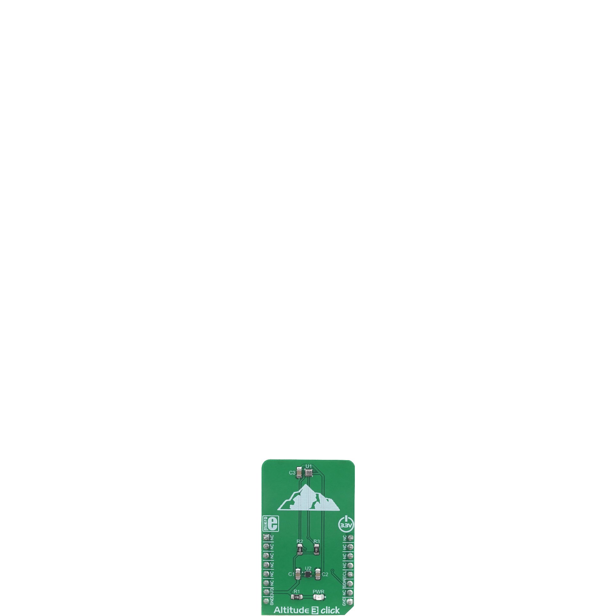
Altitude 3 Click
Dev. board
Fusion for ARM v8
Compiler
NECTO Studio
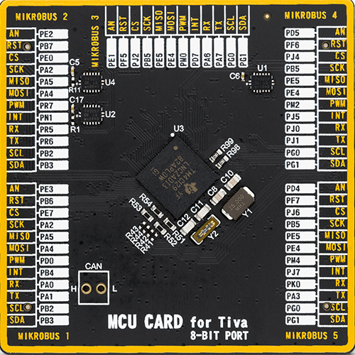
MCU
TM4C129LNCZAD
Trust in our altitude measurement solution to unlock the secrets of the skies and make informed decisions whether you're a researcher or an outdoor enthusiast
A
A
Hardware Overview
How does it work?
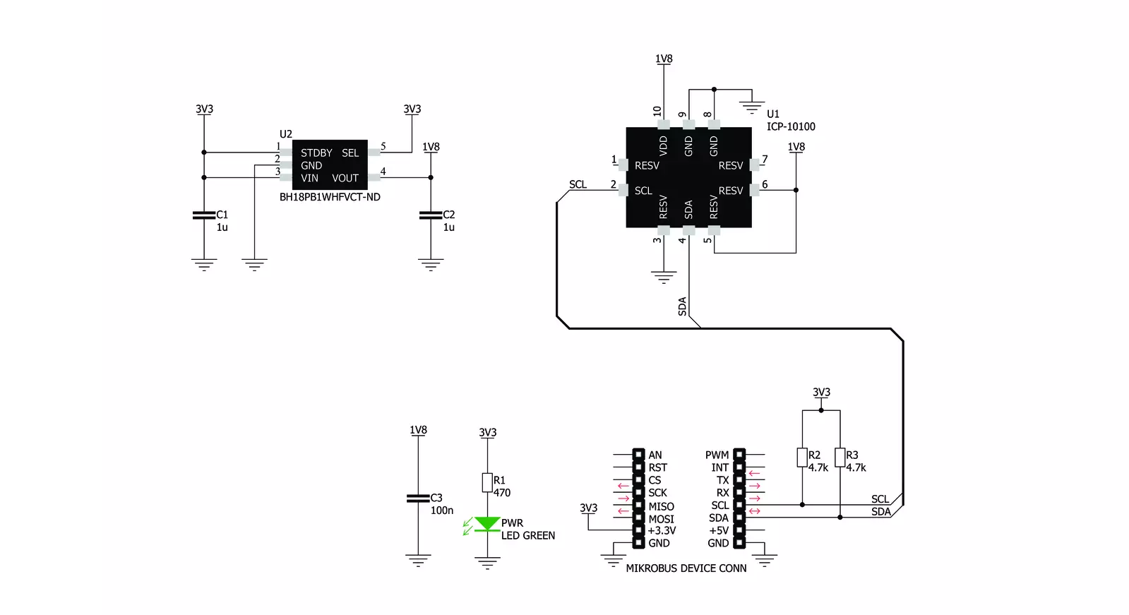
Altitude 3 Click is based on the ICP-10100, a high accuracy, low power, waterproof barometric pressure and temperature sensor from TDK corporation. The sensor is manufactured using the ultra-low noise MEMS (Micro Electro Mechanical System) capacitive technology, optimized for precise altitude measurements. It can detect pressure difference with the accuracy of ±1 Pa, which translates to an altitude resolution of less than 10cm. This makes this sensor very usable in drone applications development, allowing it to hover at a fixed altitude, or to be used as the stabilization control. Also, this sensor has a very low temperature offset of only ±0.5 Pa/°C, within the range from 25°C to 45°C. Each sensor IC is factory calibrated and the calibration parameters are stored within the OTP memory. To convert the readings into temperature and pressure values, these coefficients need to be used. The datasheet of the ICP-10100 offers formulas for these
calculations. However, Altitude 3 Click comes with a library that contains functions that encapsulate these calculations, which greatly accelerates application development. Being packaged in a waterproof casing, the ICP-10100 sensor allows it to be used under 1.5m of water for the duration of 30 minutes. However, since the Click board™ itself is not waterproof, the sensor still offers a good resistance against increased humidity and moisture. The ICP-10100 sensor offers the best performance when operated within the normal pressure and temperature conditions within the range from 0°C to 45°C, and from 95 kPa to 105 kPa. The ICP-10100 can be operated in four different modes, allowing its performace to be tailored according to specific requirements. These modes allow a compromise between high precision, low noise, output speed, and power consumption. These modes include Low Power mode (LP), Normal mode (N), Low Noise mode
(LN) and Ultra Low Noise mode (ULN). The datasheet of the ICP-10100 contains a table that displays the conversion time, current consumption, and pressure measurement noise for each of these modes, allowing the optimal mode to be chosen. This Click board™ uses the I2C protocol to communicate with the host MCU. It contains two pull-up resistors for each of the I2C lines. The ICP-10100 is operated with only 1.8V. To provide this voltage, an additional IC had to be used. The BH18PB1WHFVCT is a small LDO regulator, providing the required voltage for the ICP-10100. Both I2C lines of the pressure sensor IC are pulled up to a 3.3V power rail though, allowing it to be operated by most MCUs that typically use 3.3V logic voltage levels. Please note that the Click board™ supports only 3.3V MCUs and it is not intended to be controlled with MCUs that use 5V without a proper level shifting circuitry.


Features overview
Development board
Fusion for ARM v8 is a development board specially designed for the needs of rapid development of embedded applications. It supports a wide range of microcontrollers, such as different ARM® Cortex®-M based MCUs regardless of their number of pins, and a broad set of unique functions, such as the first-ever embedded debugger/programmer over WiFi. The development board is well organized and designed so that the end-user has all the necessary elements, such as switches, buttons, indicators, connectors, and others, in one place. Thanks to innovative manufacturing technology, Fusion for ARM v8 provides a fluid and immersive working experience, allowing access anywhere and under any
circumstances at any time. Each part of the Fusion for ARM v8 development board contains the components necessary for the most efficient operation of the same board. An advanced integrated CODEGRIP programmer/debugger module offers many valuable programming/debugging options, including support for JTAG, SWD, and SWO Trace (Single Wire Output)), and seamless integration with the Mikroe software environment. Besides, it also includes a clean and regulated power supply module for the development board. It can use a wide range of external power sources, including a battery, an external 12V power supply, and a power source via the USB Type-C (USB-C) connector.
Communication options such as USB-UART, USB HOST/DEVICE, CAN (on the MCU card, if supported), and Ethernet is also included. In addition, it also has the well-established mikroBUS™ standard, a standardized socket for the MCU card (SiBRAIN standard), and two display options for the TFT board line of products and character-based LCD. Fusion for ARM v8 is an integral part of the Mikroe ecosystem for rapid development. Natively supported by Mikroe software tools, it covers many aspects of prototyping and development thanks to a considerable number of different Click boards™ (over a thousand boards), the number of which is growing every day.

Microcontroller Overview
MCU Card / MCU
Type
8th Generation
Architecture
ARM Cortex-M4
MCU Memory (KB)
1024
Silicon Vendor
Texas Instruments
Pin count
212
RAM (Bytes)
262144
Used MCU Pins
mikroBUS™ mapper
Take a closer look
Click board™ Schematic
Step by step
Project assembly

Start by selecting your development board and Click board™. Begin with the Fusion for ARM v8 as your development board.


Software Support
Library Description
This library contains API for Altitude 3 Click driver.
Key functions:
altitude3_soft_reset- Function sends a command to perform a SW Reset of the devicealtitude3_read_adc_results- Function reads results of AD conversion, which consists of the 16bit temperature and 24bit pressure data in determined orderaltitude3_get_data- Function performs a calibration data reading, only once, and then reads a temperature and pressure data and calculates these values to standard units
Open Source
Code example
The complete application code and a ready-to-use project are available through the NECTO Studio Package Manager for direct installation in the NECTO Studio. The application code can also be found on the MIKROE GitHub account.
/*!
 * \file
 * \brief Altitude3 Click example
 *
 * # Description
 * This application enables high-resolution barometric pressure measurement.
 *
 * The demo application is composed of two sections :
 *
 * ## Application Init
 * Initializes I2C interface and performs a SW Reset of the device.
 *
 * ## Application Task
 * Selects the desired measurement mode and data reading order, and after that
 * calculates the temperature, pressure and altitude data to standard units and shows results to uart terminal.
 *
 *
 * \author MikroE Team
 *
 */
// ------------------------------------------------------------------- INCLUDES

#include "board.h"
#include "log.h"
#include "altitude3.h"

// ------------------------------------------------------------------ VARIABLES

static altitude3_t altitude3;
static log_t logger;

// ------------------------------------------------------ APPLICATION FUNCTIONS

void application_init ( void )
{
    log_cfg_t log_cfg;
    altitude3_cfg_t cfg;

    /**
     * Logger initialization.
     * Default baud rate: 115200
     * Default log level: LOG_LEVEL_DEBUG
     * @note If USB_UART_RX and USB_UART_TX
     * are defined as HAL_PIN_NC, you will
     * need to define them manually for log to work.
     * See @b LOG_MAP_USB_UART macro definition for detailed explanation.
     */
    LOG_MAP_USB_UART( log_cfg );
    log_init( &logger, &log_cfg );
    log_info( &logger, "---- Application Init ----" );

    //  Click initialization.

    altitude3_cfg_setup( &cfg );
    ALTITUDE3_MAP_MIKROBUS( cfg, MIKROBUS_1 );
    altitude3_init( &altitude3, &cfg );

    altitude3_default_cfg ( &altitude3 );

    log_printf( &logger, "** Altitude 3 Click is initialized **\r\n\r\n" );
}

void application_task ( void )
{
    uint8_t response;

    response = altitude3_measurement_mode( &altitude3, ALTITUDE3_NORMAL_T_FIRST );

    Delay_ms ( 100 );

    response = altitude3_get_data( &altitude3, response );

    if ( response != ALTITUDE3_ERROR )
    {
        log_printf( &logger, "Temperature is : %d C\r\n", ( int16_t ) altitude3.sens_data.temperature );

        log_printf( &logger, "Pressure is : %u  mbar[hPa]\r\n", ( uint16_t ) altitude3.sens_data.pressure );

        log_printf( &logger, "Altitude is : %d m\r\n\r\n", ( int16_t ) altitude3.sens_data.altitude );

        Delay_ms ( 400 );
    }
}

int main ( void )
{
    /* Do not remove this line or clock might not be set correctly. */
    #ifdef PREINIT_SUPPORTED
    preinit();
    #endif

    application_init( );

    for ( ; ; )
    {
        application_task( );
    }

    return 0;
}

// ------------------------------------------------------------------------ END
Additional Support
Resources
Category:Pressure


