Maintain controlled environments by monitoring pressure variations with ICP-10111 and STM32F417ZG
Barometers: Nature's weather whisperers

Published Oct 14, 2023
Click board™
Barometer 4 Click
Dev. board
UNI-DS v8
Compiler
NECTO Studio
MCU
STM32F417ZG
Discover the versatility of barometers in diverse fields, from agriculture to aviation, as they contribute to efficiency and precision in a wide range of applications
A
A
Hardware Overview
How does it work?
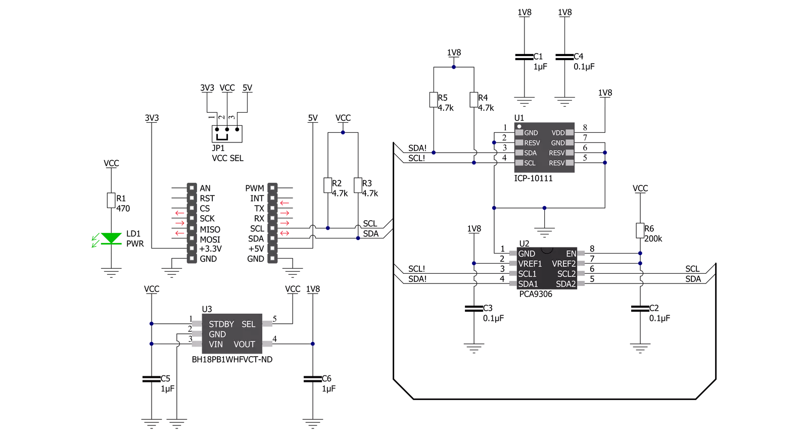
Barometer 4 Click is based on the ICP-10111, an ultra-low power, low noise, digital output barometric pressure and temperature sensor from TDK InvenSense. It is based on an innovative MEMS capacitive pressure sensor technology that can measure pressure from 30kPa up to 110kPa with an accuracy of ±1Pa over a wide operating temperature range at the industry’s lowest power. This high-accuracy MEMS capacitive pressure sensor can also measure altitude differentials down to 8.5cm without the penalty of increased power consumption or reduced sensor throughput. The ICP-10111 also offers industry-leading temperature stability of the pressure sensor with a temperature coefficient offset of
±0.5Pa/°C. The high accuracy, temperature stability, and low power consumption offered by ICP-10111 make it ideally suited for applications such as drone flight control and stabilization, indoor/outdoor navigation, sports and fitness activity monitoring, and battery-powered IoT. The ICP-10111 also requires a supply voltage of 1.8V to work regularly. Therefore, a small LDO regulator, BH18PB1WHFV from Rohm Semiconductor, provides 1.8V out of mikroBUS™ power rails. This LDO cuts power consumption by lowering its current consumption to approximately 2μA when the application operates in the Standby state. Barometer 4 Click communicates with MCU using a standard I2C 2-Wire interface that supports
400kHz Fast Mode operation. Since the sensor for operation requires a 1.8V logic voltage level only, this Click board™ also features the PCA9306 voltage-level translator from Texas Instruments. The I2C interface bus lines are routed to the dual bidirectional voltage-level translator, allowing this Click board™ to work properly with both 3.3V and 5V MCUs. This Click board™ can operate with either 3.3V or 5V logic voltage levels selected via the VCC SEL jumper. This way, both 3.3V and 5V capable MCUs can use the communication lines properly. Also, this Click board™ comes equipped with a library containing easy-to-use functions and an example code that can be used as a reference for further development.


Features overview
Development board
UNI-DS v8 is a development board specially designed for the needs of rapid development of embedded applications. It supports a wide range of microcontrollers, such as different STM32, Kinetis, TIVA, CEC, MSP, PIC, dsPIC, PIC32, and AVR MCUs regardless of their number of pins, and a broad set of unique functions, such as the first-ever embedded debugger/programmer over WiFi. The development board is well organized and designed so that the end-user has all the necessary elements, such as switches, buttons, indicators, connectors, and others, in one place. Thanks to innovative manufacturing technology, UNI-DS v8 provides a fluid and immersive working experience, allowing access anywhere and under any
circumstances at any time. Each part of the UNI-DS v8 development board contains the components necessary for the most efficient operation of the same board. An advanced integrated CODEGRIP programmer/debugger module offers many valuable programming/debugging options, including support for JTAG, SWD, and SWO Trace (Single Wire Output)), and seamless integration with the Mikroe software environment. Besides, it also includes a clean and regulated power supply module for the development board. It can use a wide range of external power sources, including a battery, an external 12V power supply, and a power source via the USB Type-C (USB-C) connector. Communication options such as USB-UART, USB
HOST/DEVICE, CAN (on the MCU card, if supported), and Ethernet is also included. In addition, it also has the well-established mikroBUS™ standard, a standardized socket for the MCU card (SiBRAIN standard), and two display options for the TFT board line of products and character-based LCD. UNI-DS v8 is an integral part of the Mikroe ecosystem for rapid development. Natively supported by Mikroe software tools, it covers many aspects of prototyping and development thanks to a considerable number of different Click boards™ (over a thousand boards), the number of which is growing every day.

Microcontroller Overview
MCU Card / MCU
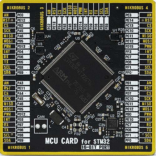
Type
8th Generation
Architecture
ARM Cortex-M4
MCU Memory (KB)
1024
Silicon Vendor
STMicroelectronics
Pin count
144
RAM (Bytes)
196608
Used MCU Pins
mikroBUS™ mapper
Take a closer look
Click board™ Schematic
Step by step
Project assembly

Start by selecting your development board and Click board™. Begin with the UNI-DS v8 as your development board.


Software Support
Library Description
This library contains API for Barometer 4 Click driver.
Key functions:
barometer4_get_pressure_and_temperature- Barometer 4 get pressure and temperature functionbarometer4_get_raw_data- Barometer 4 get RAW data functionbarometer4_soft_reset- Barometer 4 software reset function
Open Source
Code example
The complete application code and a ready-to-use project are available through the NECTO Studio Package Manager for direct installation in the NECTO Studio. The application code can also be found on the MIKROE GitHub account.
/*!
 * @file main.c
 * @brief Barometer4 Click example
 *
 * # Description
 * This library contains API for the Barometer 4 Click driver.
 * The library initializes and defines the I2C bus drivers
 * to write and read data from registers.
 * This demo application shows an example of
 * atmospheric pressure and temperature measurement.
 *
 * The demo application is composed of two sections :
 *
 * ## Application Init
 * The initialization of the I2C module and log UART.
 * After driver initialization and default settings,
 * the app display device ID.
 *
 * ## Application Task
 * This is an example that shows the use of a Barometer 4 Click board™.
 * Logs the atmospheric pressure [ Pa ] and temperature [ degree Celsius ] data.
 * Results are being sent to the Usart Terminal where you can track their changes.
 *
 * @author Nenad Filipovic
 *
 */

#include "board.h"
#include "log.h"
#include "barometer4.h"

static barometer4_t barometer4;
static log_t logger;

void application_init ( void )
{
    log_cfg_t log_cfg;                /**< Logger config object. */
    barometer4_cfg_t barometer4_cfg;  /**< Click config object. */

    /**
     * Logger initialization.
     * Default baud rate: 115200
     * Default log level: LOG_LEVEL_DEBUG
     * @note If USB_UART_RX and USB_UART_TX
     * are defined as HAL_PIN_NC, you will
     * need to define them manually for log to work.
     * See @b LOG_MAP_USB_UART macro definition for detailed explanation.
     */
    LOG_MAP_USB_UART( log_cfg );
    log_init( &logger, &log_cfg );
    log_info( &logger, " Application Init " );

    // Click initialization.
    barometer4_cfg_setup( &barometer4_cfg );
    BAROMETER4_MAP_MIKROBUS( barometer4_cfg, MIKROBUS_1 );
    err_t init_flag = barometer4_init( &barometer4, &barometer4_cfg );
    if ( I2C_MASTER_ERROR == init_flag )
    {
        log_error( &logger, " Application Init Error. " );
        log_info( &logger, " Please, run program again... " );

        for ( ; ; );
    }

    barometer4_default_cfg ( &barometer4 );
    log_info( &logger, " Application Task " );
    log_printf( &logger, "----------------------------\r\n" );
    Delay_ms ( 100 );

    static uint16_t device_id;
    err_t err_flag = barometer4_get_device_id( &barometer4, &device_id );
    if ( BAROMETER4_ERROR == err_flag )
    {
        log_error( &logger, " Communication Error. " );
        log_info( &logger, " Please, run program again... " );

        for ( ; ; );
    }
    log_printf( &logger, " Device ID   : 0x%.4X \r\n", device_id );
    log_printf( &logger, "----------------------------\r\n" );
    Delay_ms ( 1000 );
}

void application_task ( void )
{
    static float pressure;
    static float temperature;

    barometer4_get_pressure_and_temperature( &barometer4, &pressure, &temperature );
    log_printf( &logger, " Pressure    : %.2f Pa\r\n", pressure );
    log_printf( &logger, " Temperature : %.2f C\r\n", temperature );
    log_printf( &logger, "----------------------------\r\n" );
    Delay_ms ( 1000 );
}

int main ( void )
{
    /* Do not remove this line or clock might not be set correctly. */
    #ifdef PREINIT_SUPPORTED
    preinit();
    #endif

    application_init( );

    for ( ; ; )
    {
        application_task( );
    }

    return 0;
}

// ------------------------------------------------------------------------ END
Additional Support
Resources
Category:Pressure


