Integrate fiber-optic communication using IF-D91, IF-E97 and STM32F302VC for lightning-speed data exchange
Transforming designs with fiber-optic innovation
Published Jul 22, 2025
Click board™
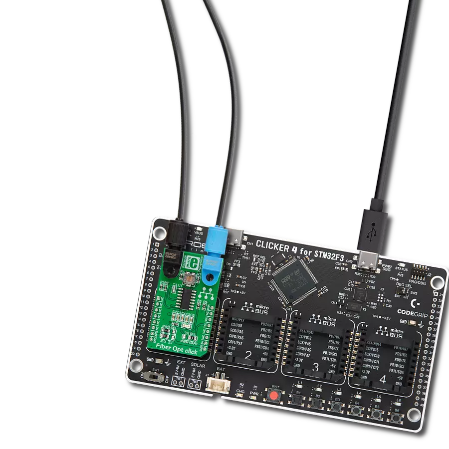
Fiber Opt click
Dev. board
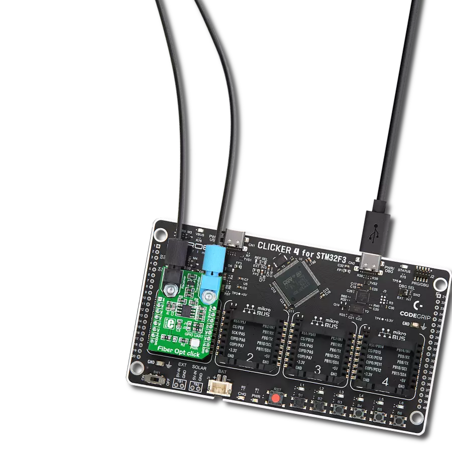
CLICKER 4 for STM32F302VCT6
Compiler
NECTO Studio
MCU
STM32F302VC
Integrate high-speed fiber-optic communication and establish reliable, secure networks to meet growing demands for rapid data exchange while enhancing overall performance and efficiency.
A
A
Hardware Overview
How does it work?
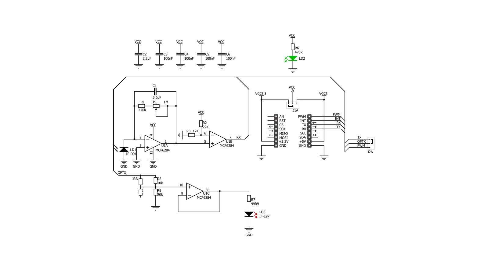
Fiber Opt Click is based on one IF-D91, a fiber-optic photodiode, and one IF-E97, a fiber-optic LED, both from Industrial Fiber Optics. The IF-D91 is a high-speed photodiode detector housed in a connector-less plastic fiber optic package. Its optical response extends from 400 to 1100nm, making it compatible with a wide range of visible and near-infrared LED and laser diode sources. The detector package features an internal micro-lens and a precision-molded PBT housing to ensure efficient optical coupling with standard 1000μm core 2.2mm jacketed plastic fiber cable capable of 100Mbps data rates. The IF-D91 can also be used for analog video links with bandwidths
up to 70MHz. The other precision-molded PBT housing with internal micro-lens, the IF-E97, is a high-optical-output visible red LED. The housing ensures efficient optical coupling with the same standard jacketed plastic fiber cable. The output spectrum is produced by a GaAlAs die, which peaks at 650nm, representing an optimal transmission window for PMMA plastic optical fiber. The visible red light has low attenuation in PMMA plastic fiber, aids troubleshooting installations, and is the main reason the IF-E97 achieves data rates of 1Mbps. This Click board™ communicates with the host MCU over selectable pins of the mikroBUS™ socket. Transmission can
be selected through the TX SEL selection jumper between the UART TX pin or PWM pin of the mikroBUS™ socket, as UART is selected by default. Received data is available on the RX pin of the mikroBUS™ socket. This Click board™ can operate with either 3.3V or 5V logic voltage levels selected via the PWR SEL jumper. This way, both 3.3V and 5V capable MCUs can use the communication lines properly. Also, this Click board™ comes equipped with a library containing easy-to-use functions and an example code that can be used, as a reference, for further development.

Features overview
Development board
Clicker 4 for STM32F3 is a compact development board designed as a complete solution, you can use it to quickly build your own gadgets with unique functionalities. Featuring a STM32F302VCT6, four mikroBUS™ sockets for Click boards™ connectivity, power managment, and more, it represents a perfect solution for the rapid development of many different types of applications. At its core, there is a STM32F302VCT6 MCU, a powerful microcontroller by STMicroelectronics, based on the high-
performance Arm® Cortex®-M4 32-bit processor core operating at up to 168 MHz frequency. It provides sufficient processing power for the most demanding tasks, allowing Clicker 4 to adapt to any specific application requirements. Besides two 1x20 pin headers, four improved mikroBUS™ sockets represent the most distinctive connectivity feature, allowing access to a huge base of Click boards™, growing on a daily basis. Each section of Clicker 4 is clearly marked, offering an intuitive and clean interface. This makes working with the development
board much simpler and thus, faster. The usability of Clicker 4 doesn’t end with its ability to accelerate the prototyping and application development stages: it is designed as a complete solution which can be implemented directly into any project, with no additional hardware modifications required. Four mounting holes [4.2mm/0.165”] at all four corners allow simple installation by using mounting screws. For most applications, a nice stylish casing is all that is needed to turn the Clicker 4 development board into a fully functional, custom design.

Microcontroller Overview
MCU Card / MCU

Architecture
ARM Cortex-M4
MCU Memory (KB)
256
Silicon Vendor
STMicroelectronics
Pin count
100
RAM (Bytes)
40960
Used MCU Pins
mikroBUS™ mapper
Take a closer look
Click board™ Schematic
Step by step
Project assembly

Start by selecting your development board and Click board™. Begin with the CLICKER 4 for STM32F302VCT6 as your development board.


Track your results in real time
Application Output
1. Application Output - In Debug mode, the 'Application Output' window enables real-time data monitoring, offering direct insight into execution results. Ensure proper data display by configuring the environment correctly using the provided tutorial.

2. UART Terminal - Use the UART Terminal to monitor data transmission via a USB to UART converter, allowing direct communication between the Click board™ and your development system. Configure the baud rate and other serial settings according to your project's requirements to ensure proper functionality. For step-by-step setup instructions, refer to the provided tutorial.

3. Plot Output - The Plot feature offers a powerful way to visualize real-time sensor data, enabling trend analysis, debugging, and comparison of multiple data points. To set it up correctly, follow the provided tutorial, which includes a step-by-step example of using the Plot feature to display Click board™ readings. To use the Plot feature in your code, use the function: plot(*insert_graph_name*, variable_name);. This is a general format, and it is up to the user to replace 'insert_graph_name' with the actual graph name and 'variable_name' with the parameter to be displayed.

Software Support
Library Description
This library contains API for Fiber Opt Click driver.
Key functions:
fiberopt_generic_write- Generic single write functionfiberopt_generic_read- Generic single read function.
Open Source
Code example
The complete application code and a ready-to-use project are available through the NECTO Studio Package Manager for direct installation in the NECTO Studio. The application code can also be found on the MIKROE GitHub account.
/*!
 * \file
 * \brief Fiber Opt Click example
 *
 * # Description
 * This example demonstrates the use of an Fiber Opt Click board by showing
 * the communication between the two Click boards.
 *
 * The demo application is composed of two sections :
 *
 * ## Application Init
 * Initalizes device and makes an initial log.
 *
 * ## Application Task
 * Depending on the selected application mode, it reads all the received data or
 * sends the desired text message with the message counter once per second.
 *
 * \author MikroE Team
 *
 */

#include "board.h"
#include "log.h"
#include "fiberopt.h"

// Comment out the line below in order to switch the application mode to receiver
#define DEMO_APP_TRANSMITTER

// Text message to send in the transmitter application mode
#define DEMO_TEXT_MESSAGE           "MIKROE - Fiber Opt Click board\r\n\0"

static fiberopt_t fiberopt;
static log_t logger;

void application_init ( void )
{
    log_cfg_t log_cfg;
    fiberopt_cfg_t cfg;

    /**
     * Logger initialization.
     * Default baud rate: 115200
     * Default log level: LOG_LEVEL_DEBUG
     * @note If USB_UART_RX and USB_UART_TX
     * are defined as HAL_PIN_NC, you will
     * need to define them manually for log to work.
     * See @b LOG_MAP_USB_UART macro definition for detailed explanation.
     */
    LOG_MAP_USB_UART( log_cfg );
    log_init( &logger, &log_cfg );
    log_info( &logger, " Application Init " );

    // Click initialization.
    fiberopt_cfg_setup( &cfg );
    FIBEROPT_MAP_MIKROBUS( cfg, MIKROBUS_1 );
    fiberopt_init( &fiberopt, &cfg );

#ifdef DEMO_APP_TRANSMITTER
    log_printf( &logger, " Application Mode: Transmitter\r\n" );
#else
    log_printf( &logger, " Application Mode: Receiver\r\n" );
#endif
    log_info( &logger, " Application Task " );
    Delay_ms ( 100 );
}

void application_task ( void )
{
#ifdef DEMO_APP_TRANSMITTER
    fiberopt_generic_write( &fiberopt, DEMO_TEXT_MESSAGE, strlen( DEMO_TEXT_MESSAGE ) );
    log_printf( &logger, "%s", ( char * ) DEMO_TEXT_MESSAGE );
    Delay_ms ( 1000 );
#else
    uint8_t rx_byte = 0;
    if ( 1 == fiberopt_generic_read( &fiberopt, &rx_byte, 1 ) )
    {
       log_printf( &logger, "%c", rx_byte );
    }
#endif
}

int main ( void )
{
    /* Do not remove this line or clock might not be set correctly. */
    #ifdef PREINIT_SUPPORTED
    preinit();
    #endif

    application_init( );

    for ( ; ; )
    {
        application_task( );
    }

    return 0;
}


// ------------------------------------------------------------------------ END
Additional Support
Resources
Category:Fiber optics