Unlock the mastery of angle detection with IIS2ICLX and STM32F207ZG
Your tilt tale

Published Sep 13, 2023
Click board™
Inclinometer 2 Click
Dev. board
Fusion for STM32 v8
Compiler
NECTO Studio
MCU
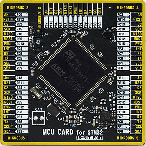
STM32F207ZG
Our advanced inclinometer solution empowers you to measure the orientation angle of objects with unrivaled precision. It's your essential tool for enhancing navigation systems, monitoring structural stability, and optimizing orientation.
A
A
Hardware Overview
How does it work?
Inclinometer 2 Click is based on the IIS2ICLX, a high-accuracy (ultra-low noise, high stability, and repeatability) and low-power two-axis linear accelerometer with digital output from STMicroelectronics. The IIS2ICLX has a selectable full scale of ±0.5/±1/±2/±3 g and is capable of providing the measured accelerations to the application over a selectable digital interface. Its high accuracy, stability over temperature, and repeatability make IIS2ICLX particularly suitable for inclination measurement applications. The IIS2ICLX has an unmatched set of embedded features (programmable FSM, Machine Learning Core, sensor hub, FIFO, event decoding, and interrupts) and delivers high accuracy and performance at low power. The sensing element is manufactured using a dedicated micromachining
process developed by STMicroelectronics to produce inertial sensors and actuators on silicon wafers. This Click board™ allows the use of both I2C and SPI interfaces with a maximum frequency of 400kHz for I2C and 10MHz for SPI communication. The selection can be made by positioning SMD jumpers labeled as COMM SEL in an appropriate position. Note that all the jumpers' positions must be on the same side, or the Click board™ may become unresponsive. While the I2C interface is selected, the IIS2ICLX allows choosing the least significant bit (LSB) of its I2C slave address using the SMD jumper labeled ADDR SEL. This Click board™ also possesses an additional interrupt signal, routed on the INT pin of the mikroBUS™ socket labeled as INT, indicating the status of the measurement process itself.
The hardware flexibility of this Click board™ allows connecting the pins with different mode connections to external sensors to expand functionalities such as adding a sensor hub. When sensor hub mode (Mode 2) is enabled, the I²C master interface for connecting external sensors is available on an onboard header reserved for the Master I2C interface, which is unpopulated by default. This Click board™ can be operated only with a 3.3V logic voltage level. The board must perform appropriate logic voltage level conversion before using MCUs with different logic levels. Also, it comes equipped with a library containing functions and an example code that can be used as a reference for further development.


Features overview
Development board
Fusion for STM32 v8 is a development board specially designed for the needs of rapid development of embedded applications. It supports a wide range of microcontrollers, such as different 32-bit ARM® Cortex®-M based MCUs from STMicroelectronics, regardless of their number of pins, and a broad set of unique functions, such as the first-ever embedded debugger/programmer over WiFi. The development board is well organized and designed so that the end-user has all the necessary elements, such as switches, buttons, indicators, connectors, and others, in one place. Thanks to innovative manufacturing technology, Fusion for STM32 v8 provides a fluid and immersive working experience, allowing
access anywhere and under any circumstances at any time. Each part of the Fusion for STM32 v8 development board contains the components necessary for the most efficient operation of the same board. An advanced integrated CODEGRIP programmer/debugger module offers many valuable programming/debugging options, including support for JTAG, SWD, and SWO Trace (Single Wire Output)), and seamless integration with the Mikroe software environment. Besides, it also includes a clean and regulated power supply module for the development board. It can use a wide range of external power sources, including a battery, an external 12V power supply, and a power source via the USB Type-C (USB-C) connector.
Communication options such as USB-UART, USB HOST/DEVICE, CAN (on the MCU card, if supported), and Ethernet is also included. In addition, it also has the well-established mikroBUS™ standard, a standardized socket for the MCU card (SiBRAIN standard), and two display options for the TFT board line of products and character-based LCD. Fusion for STM32 v8 is an integral part of the Mikroe ecosystem for rapid development. Natively supported by Mikroe software tools, it covers many aspects of prototyping and development thanks to a considerable number of different Click boards™ (over a thousand boards), the number of which is growing every day.

Microcontroller Overview
MCU Card / MCU
Type
8th Generation
Architecture
ARM Cortex-M3
MCU Memory (KB)
1024
Silicon Vendor
STMicroelectronics
Pin count
144
RAM (Bytes)
131072
Used MCU Pins
mikroBUS™ mapper
Take a closer look
Click board™ Schematic

Step by step
Project assembly

Start by selecting your development board and Click board™. Begin with the Fusion for STM32 v8 as your development board.


Track your results in real time
Application Output
1. Application Output - In Debug mode, the 'Application Output' window enables real-time data monitoring, offering direct insight into execution results. Ensure proper data display by configuring the environment correctly using the provided tutorial.

2. UART Terminal - Use the UART Terminal to monitor data transmission via a USB to UART converter, allowing direct communication between the Click board™ and your development system. Configure the baud rate and other serial settings according to your project's requirements to ensure proper functionality. For step-by-step setup instructions, refer to the provided tutorial.

3. Plot Output - The Plot feature offers a powerful way to visualize real-time sensor data, enabling trend analysis, debugging, and comparison of multiple data points. To set it up correctly, follow the provided tutorial, which includes a step-by-step example of using the Plot feature to display Click board™ readings. To use the Plot feature in your code, use the function: plot(*insert_graph_name*, variable_name);. This is a general format, and it is up to the user to replace 'insert_graph_name' with the actual graph name and 'variable_name' with the parameter to be displayed.

Software Support
Library Description
This library contains API for Inclinometer 2 Click driver.
Key functions:
inclinometer2_get_int_pin- This function returns the INT pin logic stateinclinometer2_get_accel- This function checks if the accel data is ready and than reads the accel X and Y axis in mginclinometer2_get_temperature- This function checks if the temperature data is ready and than reads the temperature in Celsius
Open Source
Code example
The complete application code and a ready-to-use project are available through the NECTO Studio Package Manager for direct installation in the NECTO Studio. The application code can also be found on the MIKROE GitHub account.
/*!
 * @file main.c
 * @brief Inclinometer2 Click example
 *
 * # Description
 * This example demonstrates the use of Inclinometer 2 Click board by reading and displaying
 * the Accel X and Y axis data (mg) and the temperature (degC) on the USB UART.
 *
 * The demo application is composed of two sections :
 *
 * ## Application Init
 * Initializes the driver and performs the Click default configuration which enables the accel
 * data ready interrupt, sets output data rate to 12.5 Hz and accel full-scale range to +-2g.
 *
 * ## Application Task
 * Waits for the data ready interrupt, then reads the values of accel X and Y axis as well as
 * the absolute temperature and displays the results on the USB UART. The data sample rate is
 * set to 12.5Hz by default, therefore the data is being read approximately every 80ms.
 *
 * @author Stefan Filipovic
 *
 */

#include "board.h"
#include "log.h"
#include "inclinometer2.h"

static inclinometer2_t inclinometer2;
static log_t logger;

void application_init ( void )
{
    log_cfg_t log_cfg;  /**< Logger config object. */
    inclinometer2_cfg_t inclinometer2_cfg;  /**< Click config object. */

    /**
     * Logger initialization.
     * Default baud rate: 115200
     * Default log level: LOG_LEVEL_DEBUG
     * @note If USB_UART_RX and USB_UART_TX
     * are defined as HAL_PIN_NC, you will
     * need to define them manually for log to work.
     * See @b LOG_MAP_USB_UART macro definition for detailed explanation.
     */
    LOG_MAP_USB_UART( log_cfg );
    log_init( &logger, &log_cfg );
    log_info( &logger, " Application Init " );

    // Click initialization.
    inclinometer2_cfg_setup( &inclinometer2_cfg );
    INCLINOMETER2_MAP_MIKROBUS( inclinometer2_cfg, MIKROBUS_1 );
    err_t init_flag  = inclinometer2_init( &inclinometer2, &inclinometer2_cfg );
    if ( ( I2C_MASTER_ERROR == init_flag ) || ( SPI_MASTER_ERROR == init_flag ) )
    {
        log_error( &logger, " Communication init." );
        for ( ; ; );
    }

    if ( INCLINOMETER2_ERROR == inclinometer2_default_cfg ( &inclinometer2 ) )
    {
        log_error( &logger, " Default configuration." );
        for ( ; ; );
    }

    log_info( &logger, " Application Task " );
}

void application_task ( void )
{
    // Wait for accel data ready indication
    while ( !inclinometer2_get_int_pin ( &inclinometer2 ) );

    float x_axis, y_axis;
    if ( INCLINOMETER2_OK == inclinometer2_get_accel ( &inclinometer2, &x_axis, &y_axis ) )
    {
        log_printf( &logger, " X: %.2f mg\r\n", x_axis );
        log_printf( &logger, " Y: %.2f mg\r\n", y_axis );
    }
    float temperature;
    if ( INCLINOMETER2_OK == inclinometer2_get_temperature ( &inclinometer2, &temperature ) )
    {
        log_printf( &logger, " Temperature: %.2f C\r\n\n", temperature );
    }
}

int main ( void )
{
    /* Do not remove this line or clock might not be set correctly. */
    #ifdef PREINIT_SUPPORTED
    preinit();
    #endif

    application_init( );

    for ( ; ; )
    {
        application_task( );
    }

    return 0;
}

// ------------------------------------------------------------------------ END


