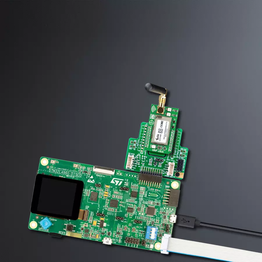
Collect and transmit data in various industrial settings with LE70-868 and STM32L496AG
Short-range RF (Radio Frequency) communication specifically made for use in the 868MHz
Published Jul 22, 2025
Click board™
tRF Click
Dev. board
Discovery kit with STM32L496AG MCU
Compiler
NECTO Studio
MCU
STM32L496AG
Add short-range RF communication capabilities to a wide range of applications, particularly those focused on monitoring and control within the ISM band
A
A
Hardware Overview
How does it work?
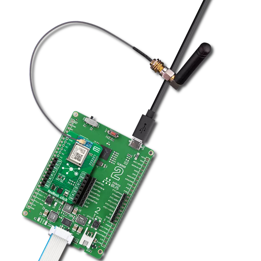
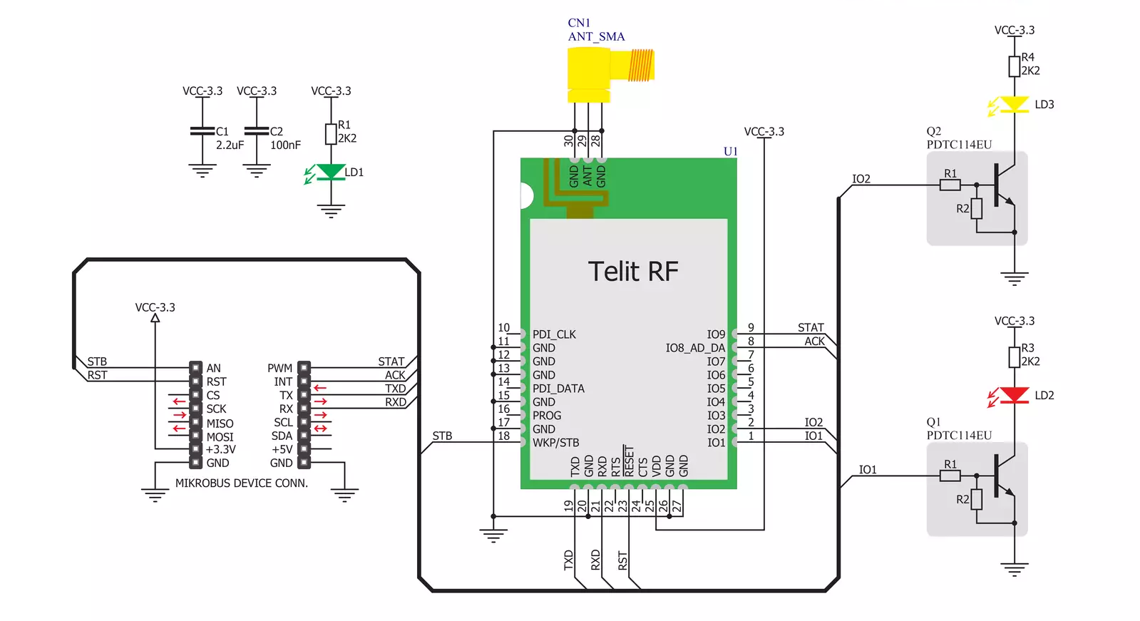
tRF Click is based on the LE70-868, a short-range wireless module from Telit. Due to its robustness and simplicity, it is ideally suited for replacing communication over cables, such as RS485 links (Profibus, Modbus) and half-duplex RS232 links, with wireless technology. With features such as Listen Before Talk (LBT), AES 128 encryption, excellent RX sensitivity of -117 dBm, 15 to 27 dBm output power, error reporting, and more, it is a perfect choice for establishing secure and reliable long-range network coverage, even in noisy environments. This module is composed of digital and RF sections. The RF section is responsible for frequency synthesis, packet handling, power amplification, and low noise reception. This module has a maximum power of 500mW, staying compliant with the ERC recommendation 70-03, Annex 1. The digital section takes care of all the I/O management and communication interfaces. The embedded MCU with the Telit software stack is also a part of this section. The module can be switched to command mode when it receives the command string (+++) via the UART. While configured to work in a command mode, it is possible to set the values of the registers. The radio communication is stopped while in this mode. The LE70-868 RF module documentation shows a list of registers, allowing a simplified device configuration. This module can operate in three different modes. In Transparent mode, its default mode, data is sent without addressing or encapsulation. Data sent to the UART RX pin of the module is sent over the air transparently as it is, where up to 115.2 kbps communication speed via UART is supported. All modules in range operating
on the same radio frequency can receive the data. The Addressed Secured mode uses frame addressing, CRC check, and acknowledgment. It allows a multipoint network to be realized, in which every module can communicate with other network modules. This mode also allows telemetry commands to be sent over the network and supports broadcasting (when sending data at address 0). Data is buffered before sending, so the frames should remain small enough to fit in the buffer. The Smart Repeater mode allows data communication between the coordinator and the end nodes, extending the function of the Addressed Secured mode. It allows every type of network distribution to be established - star topology, line topology, and a combination of these two. It can be used to extend the range of the network. Some additional features include LBT (Listen Before Talk), a feature that performs radio frequency scanning before it sends data, ensuring the radio band is free - avoiding data collisions. It works for both Transparent and Addressed modes. AES 128-bit data encryption helps achieve the required network security, while the Wake on Radio feature allows low power consumption, allowing modules to remain in Sleep mode, waking up periodically. The module wakes up entirely and processes the message when valid frames are received. As mentioned, tRF click uses the UART interface to communicate with the host MCU, supporting speed from 1.2 kbps to 115.2 kbps. In addition, the module is equipped with several configurable I/O pins. By default, they are used by the module to report status or as the control inputs. The IO9 pin is routed to the mikroBUS™ PWM pin labeled as
STS. This pin goes HIGH, during transmission over the serial port. While idle, it stays at the LOW logic level. The IO8 pin is routed to the mikroBUS™ INT pin labeled as ACK. In Addressed Secured mode, this signal goes to logic HIGH when an ACK notification is not received after frame transmission and repetition. The WKP/STB pin is used to wake the module or put it into standby mode. When the standby mode register S240 has the bit 0 set, while this pin stays at a HIGH logic level, the module will be in standby mode. The module will wake on the falling edge of this pin. It is routed to the mikroBUS™ AN pin labeled as STB. The #RESET pin is internally pulled up with a resistor. A LOW logic level on this pin will reset the embedded MCU of the module. It is routed to the RST pin of the mikroBUS™. The IO1 and IO2 pins are used to report network status by LEDs. The IO1 pin is routed to a red LED labeled TX, used to report any radio transmission from the module. The IO2 pin is routed to the yellow LED labeled RX, which reports any radio reception before the application layer processes it, activated when registers S261 and S262 are set to 0, respectively. SMA antenna connector is also included, allowing an 868MHz antenna to be connected for the optimal range of the module. This Click board™ can be operated only with a 3.3V logic voltage level. The board must perform appropriate logic voltage level conversion before using MCUs with different logic levels. Also, it comes equipped with a library containing functions and an example code that can be used as a reference for further development.

Features overview
Development board
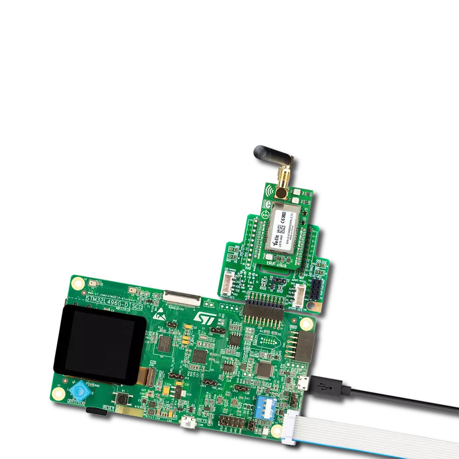
The 32L496GDISCOVERY Discovery kit serves as a comprehensive demonstration and development platform for the STM32L496AG microcontroller, featuring an Arm® Cortex®-M4 core. Designed for applications that demand a balance of high performance, advanced graphics, and ultra-low power consumption, this kit enables seamless prototyping for a wide range of embedded solutions. With its innovative energy-efficient
architecture, the STM32L496AG integrates extended RAM and the Chrom-ART Accelerator, enhancing graphics performance while maintaining low power consumption. This makes the kit particularly well-suited for applications involving audio processing, graphical user interfaces, and real-time data acquisition, where energy efficiency is a key requirement. For ease of development, the board includes an onboard ST-LINK/V2-1
debugger/programmer, providing a seamless out-of-the-box experience for loading, debugging, and testing applications without requiring additional hardware. The combination of low power features, enhanced memory capabilities, and built-in debugging tools makes the 32L496GDISCOVERY kit an ideal choice for prototyping advanced embedded systems with state-of-the-art energy efficiency.

Microcontroller Overview
MCU Card / MCU

Architecture
ARM Cortex-M4
MCU Memory (KB)
1024
Silicon Vendor
STMicroelectronics
Pin count
169
RAM (Bytes)
327680
You complete me!
Accessories
868MHz right-angle rubber antenna is a compact and versatile solution for wireless communication. Operating within the frequency range of 868-915MHz, it ensures optimal signal reception and transmission. With a 50-ohm impedance, it's compatible with various devices and systems. This antenna boasts a 2dB gain, enhancing signal strength and extending communication range. Its vertical polarization further contributes to signal clarity. Designed to handle up to 50W of input power, it's a robust choice for various applications. Measuring just 48mm in length, this antenna is both discreet and practical. Its SMA male connector ensures a secure and reliable connection to your equipment. Whether you're working with IoT devices, remote sensors, or other wireless technologies, the 868MHz right-angle antenna offers the performance and flexibility you need for seamless communication.

Used MCU Pins
mikroBUS™ mapper
Take a closer look
Click board™ Schematic
Step by step
Project assembly

Start by selecting your development board and Click board™. Begin with the Discovery kit with STM32L496AG MCU as your development board.


Software Support
Library Description
This library contains API for tRF Click driver.
Key functions:
trf_generic_single_read- Generic single read function.trf_generic_single_write- Generic single write function.trf_generic_multi_write- Generic multi write function.
Open Source
Code example
The complete application code and a ready-to-use project are available through the NECTO Studio Package Manager for direct installation in the NECTO Studio. The application code can also be found on the MIKROE GitHub account.
/*!
 * \file
 * \brief Trf Click example
 *
 * # Description
 * This is a example which demonstrates the use of Trf Click board.
 *
 * The demo application is composed of two sections :
 *
 * ## Application Init
 * Configuring Clicks and log objects.
 *
 * ## Application Task
 * Checks if new data byte have received in rx buffer (ready for reading),
 * and if ready than reads one byte from rx buffer. In second case aplication task writes
 * message data via UART.
 *
 * \author MikroE Team
 *
 */
// ------------------------------------------------------------------- INCLUDES

#include "board.h"
#include "log.h"
#include "trf.h"

// ------------------------------------------------------------------ VARIABLES

#define DEMO_APP_RECEIVER
//#define DEMO_APP_TRANSMITER

static trf_t trf;
static log_t logger;

static char demo_message[ 9 ] = { 'M', 'i', 'k', 'r', 'o', 'E', 13, 10, 0 };

// ------------------------------------------------------ APPLICATION FUNCTIONS

void application_init ( void )
{
    log_cfg_t log_cfg;
    trf_cfg_t cfg;

    /**
     * Logger initialization.
     * Default baud rate: 115200
     * Default log level: LOG_LEVEL_DEBUG
     * @note If USB_UART_RX and USB_UART_TX
     * are defined as HAL_PIN_NC, you will
     * need to define them manually for log to work.
     * See @b LOG_MAP_USB_UART macro definition for detailed explanation.
     */
    LOG_MAP_USB_UART( log_cfg );
    log_init( &logger, &log_cfg );
    log_info( &logger, "---- Application Init ----" );

    //  Click initialization.

    trf_cfg_setup( &cfg );
    TRF_MAP_MIKROBUS( cfg, MIKROBUS_1 );
    trf_init( &trf, &cfg );

    Delay_ms ( 100 );
}

void application_task ( void )
{
    char tmp;
    uint8_t cnt;

#ifdef DEMO_APP_RECEIVER

    // RECEIVER - UART polling

    tmp =  trf_generic_single_read( &trf );
    log_printf( &logger, " %c ", tmp );

#endif
#ifdef DEMO_APP_TRANSMITER

    // TRANSMITER - TX each 2 sec

    for ( cnt = 0; cnt < 8; cnt ++ )
    {
        trf_generic_single_write( &trf, demo_message[ cnt ] );
        Delay_ms ( 100 );
    }

    Delay_ms ( 1000 );
    Delay_ms ( 1000 );

#endif
}

int main ( void )
{
    /* Do not remove this line or clock might not be set correctly. */
    #ifdef PREINIT_SUPPORTED
    preinit();
    #endif

    application_init( );

    for ( ; ; )
    {
        application_task( );
    }

    return 0;
}


// ------------------------------------------------------------------------ END
Additional Support
Resources
Category:Sub-1 GHz Transceievers