Experience the future of wireless technology with SP1ML-915 and STM32F302VC
Connecting your world, beyond boundaries
Published Jul 22, 2025
Click board™
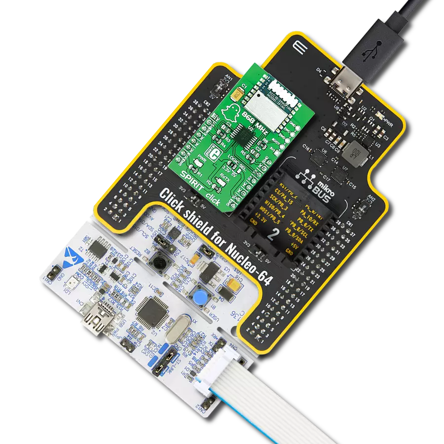
SPIRIT 2 Click
Dev. board
CLICKER 4 for STM32F302VCT6
Compiler
NECTO Studio
MCU
STM32F302VC
Expect excellence in every byte of data transmission with our fully integrated RF module at the 915MHz ISM band, revolutionizing how you exchange information.
A
A
Hardware Overview
How does it work?
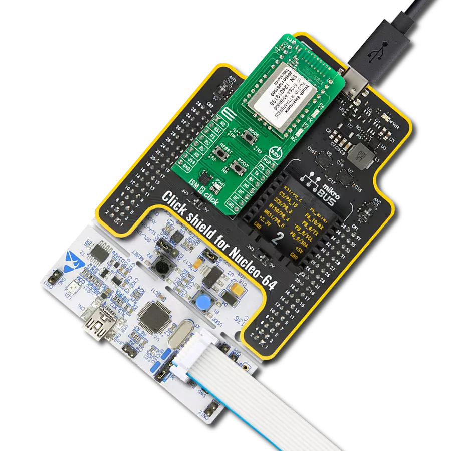
SPIRIT 2 Click is based on the SP1ML-915, a low power RF module with integrated MCU, from STMicroelectronics. The module incorporates all the necessary components packed in a very compact size of 14 x 13.4 x 2.5 mm. The STM32L1, an integrated 32-bit MCU is designed with the maximized power saving in mind, offering many power saving features. This allows even lower power consumption for the entire module, providing data rates up to 500 kbps. RF signal modulation schemes facilitate any RF transmission requirements, allowing fine-tuning of both the range and the power consumption. The primary function of the SP1ML-915 module is to be used as a wireless serial cable replacement. The Click board™ features the SWD compatible programming header, allowing custom firmware to be uploaded to the integrated MCU. However, that may destroy the factory firmware and void the warranty. Offering a simple UART interface, combined with the lowered power consumption, it represents a perfect solution for adding wireless connectivity, especially to IoT applications. Since the
module is designed to be used without an extensive RF communication experience, it is very simple to be used. The Click board™ offers two modes of operation: Operating mode and Command mode. In operating mode, data received from the host on the UART interface will be wirelessly transmitted by the module using the current configuration settings for frequency, data rate, modulation and output power. Also, any data received by the module that meets the configured filtering criteria, will be output to the UART interface. Command mode allows configuration of the SP1ML-915 module. When the Click board™ receives an escape sequence "+++", followed by at least of 500ms of RX inactivity, it will enter the Command mode. By using a number of simple AT commands, the developer has the possibility to configure the operating parameters of the device. The complete list of AT commands is provided in the datasheet of the SP1ML-915 module. A note should be taken not to send the escape sequence during the normal operation, if entering the Command mode is not intended. Besides using the aforementioned escape sequence, the module
can be put into the Command mode by driving the CMD pin of the Click board™ to a LOW logic level. A HIGH logic level on this pin will force the Click board™ into the Operating mode. The Click board™ should be reset after changing the state on this pin. To reset the SP1ML-915 module, a LOW logic level to the RST pin of the Click board™ should be applied. While there is a LOW logic level present on the RST pin, the SP1ML-915module will be held in the RESET mode. SHD pin of the Click board™ will drive the Click board™ into the power down mode by applying the LOW logic level on it. A HIGH logic level will wake-up the device. The data traffic is indicated by a LED labeled as TX/RX. However, the indicator should be enabled to use it. Consult the datasheet of the SP1ML-915 for more information. The Click board™ can be interfaced with both 3.3V and 5V MCUs without the need for any external components. Thanks to the TXB0106, 6-Bit bidirectional voltage-level translator, the Click board™ can be simply used with a wide range of different MCUs.

Features overview
Development board
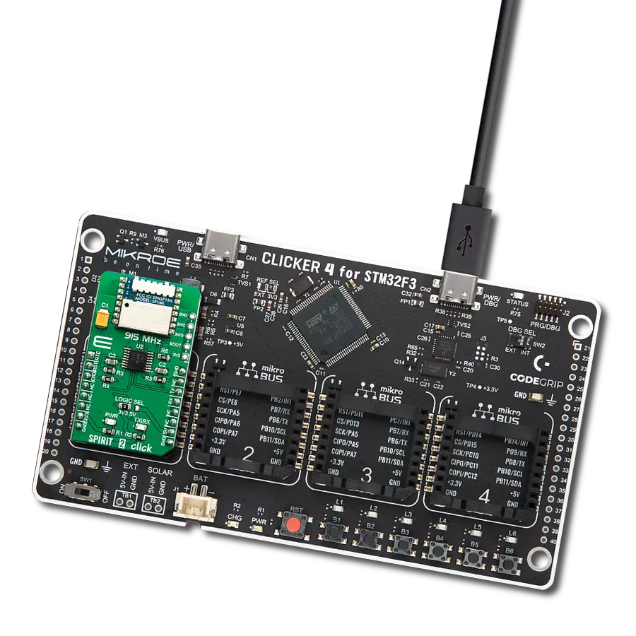
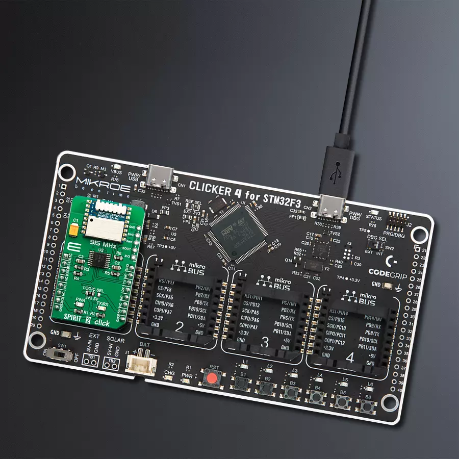
Clicker 4 for STM32F3 is a compact development board designed as a complete solution, you can use it to quickly build your own gadgets with unique functionalities. Featuring a STM32F302VCT6, four mikroBUS™ sockets for Click boards™ connectivity, power managment, and more, it represents a perfect solution for the rapid development of many different types of applications. At its core, there is a STM32F302VCT6 MCU, a powerful microcontroller by STMicroelectronics, based on the high-
performance Arm® Cortex®-M4 32-bit processor core operating at up to 168 MHz frequency. It provides sufficient processing power for the most demanding tasks, allowing Clicker 4 to adapt to any specific application requirements. Besides two 1x20 pin headers, four improved mikroBUS™ sockets represent the most distinctive connectivity feature, allowing access to a huge base of Click boards™, growing on a daily basis. Each section of Clicker 4 is clearly marked, offering an intuitive and clean interface. This makes working with the development
board much simpler and thus, faster. The usability of Clicker 4 doesn’t end with its ability to accelerate the prototyping and application development stages: it is designed as a complete solution which can be implemented directly into any project, with no additional hardware modifications required. Four mounting holes [4.2mm/0.165”] at all four corners allow simple installation by using mounting screws. For most applications, a nice stylish casing is all that is needed to turn the Clicker 4 development board into a fully functional, custom design.

Microcontroller Overview
MCU Card / MCU

Architecture
ARM Cortex-M4
MCU Memory (KB)
256
Silicon Vendor
STMicroelectronics
Pin count
100
RAM (Bytes)
40960
Used MCU Pins
mikroBUS™ mapper
Take a closer look
Click board™ Schematic

Step by step
Project assembly

Start by selecting your development board and Click board™. Begin with the CLICKER 4 for STM32F302VCT6 as your development board.


Software Support
Library Description
This library contains API for SPIRIT 2 Click driver.
Key functions:
spirit2_power_module- Function for power modespirit2_reset- Function for resetingspirit2_set_mode- Function for setting mode
Open Source
Code example
The complete application code and a ready-to-use project are available through the NECTO Studio Package Manager for direct installation in the NECTO Studio. The application code can also be found on the MIKROE GitHub account.
/*!
 * @file main.c
 * @brief SPIRIT 2 Click Example.
 *
 * # Description
 * This example reads and processes data from SPIRIT 2 Click.
 *
 * The demo application is composed of two sections :
 *
 * ## Application Init
 * Initializes the driver and configures the Click board.
 *
 * ## Application Task
 * Depending on the selected mode, it reads all the received data or sends the desired message
 * every 2 seconds.
 *
 * ## Additional Function
 * - static err_t spirit2_process ( void )
 *
 * @author Jelena Milosavljevic
 *
 */

// ------------------------------------------------------------------- INCLUDES

#include "board.h"
#include "log.h"
#include "spirit2.h"

#define PROCESS_BUFFER_SIZE    500
#define PROCESS_COUNTER        20

#define TEXT_TO_SEND           "MikroE - SPIRIT 2 Click board\r\n"

#define DEMO_APP_RECEIVER
//#define DEMO_APP_TRANSMITTER

static spirit2_t spirit2;
static log_t logger;

static char app_buf[ PROCESS_BUFFER_SIZE ] = { 0 };
static int32_t app_buf_len = 0;
static int32_t app_buf_cnt = 0;

/**
 * @brief SPIRIT2 2 data reading function.
 * @details This function reads data from device and concatenates data to application buffer.
 *
 * @return @li @c  0 - Read some data.
 *         @li @c -1 - Nothing is read.
 *         @li @c -2 - Application buffer overflow.
 *
 * See #err_t definition for detailed explanation.
 * @note None.
 */
static void spirit2_process ( void );

// ------------------------------------------------------ APPLICATION FUNCTIONS

void application_init ( void )
{
    log_cfg_t log_cfg;
    spirit2_cfg_t cfg;

    /**
     * Logger initialization.
     * Default baud rate: 115200
     * Default log level: LOG_LEVEL_DEBUG
     * @note If USB_UART_RX and USB_UART_TX
     * are defined as HAL_PIN_NC, you will
     * need to define them manually for log to work.
     * See @b LOG_MAP_USB_UART macro definition for detailed explanation.
     */
    LOG_MAP_USB_UART( log_cfg );
    log_init( &logger, &log_cfg );
    log_info( &logger, "---- Application Init ----" );

    //  Click initialization.

    spirit2_cfg_setup( &cfg );
    SPIRIT2_MAP_MIKROBUS( cfg, MIKROBUS_1 );
    spirit2_init( &spirit2, &cfg );
    Delay_ms ( 1000 );

    log_info( &logger, "---- Configuring the module ----" );
    spirit2_power_module( &spirit2, SPIRIT2_MODULE_WAKE_UP );
    spirit2_reset( &spirit2 );
    spirit2_set_mode( &spirit2, SPIRIT2_OPERATING_MODE );
    Delay_ms ( 1000 );
    log_printf( &logger, "COMMAND MODE\r\n" );
    spirit2_send_cmd( &spirit2, SPIRIT2_CMD_ENTER_COMMAND_MODE );
    spirit2_process( );
    log_printf( &logger, "FIRMWARE VERSION\r\n" );
    spirit2_send_cmd( &spirit2, SPIRIT2_CMD_READ_MODULE_VERSION );
    spirit2_process( );
    log_printf( &logger, "TXRX LED - OPEN DRAIN OUTPUT\r\n" );
    spirit2_send_cmd_with_parameter( &spirit2, SPIRIT2_CMD_CFG_TXRX_LED, SPIRIT2_PCFG_TXRXLED_OPEN_DRAIN );
    spirit2_process( );
    log_printf( &logger, "STORE CONFIG\r\n" );
    spirit2_send_cmd( &spirit2, SPIRIT2_CMD_STORE_CURRENT_CONFIG );
    spirit2_process( );
    log_printf( &logger, "OPERATING MODE\r\n" );
    spirit2_send_cmd( &spirit2, SPIRIT2_CMD_ENTER_OPERATING_MODE );
    spirit2_process( );
    log_info( &logger, "---- The module has been configured ----" );
#ifdef DEMO_APP_RECEIVER
    log_info( &logger, "---- RECEIVER MODE ----" );
#endif
#ifdef DEMO_APP_TRANSMITTER
    log_info( &logger, "---- TRANSMITTER MODE ----" );
#endif
    Delay_ms ( 1000 );
}

void application_task ( void ) {
#ifdef DEMO_APP_RECEIVER
    spirit2_process( );
#endif

#ifdef DEMO_APP_TRANSMITTER
    spirit2_generic_write( &spirit2, TEXT_TO_SEND, strlen( TEXT_TO_SEND ) );
    log_info( &logger, "---- The message has been sent ----" );
    Delay_ms ( 1000 );
    Delay_ms ( 1000 );
#endif
}

int main ( void )
{
    /* Do not remove this line or clock might not be set correctly. */
    #ifdef PREINIT_SUPPORTED
    preinit();
    #endif

    application_init( );

    for ( ; ; )
    {
        application_task( );
    }

    return 0;
}

static void spirit2_process ( void ) {
    int32_t rsp_size;

    char uart_rx_buffer[ PROCESS_BUFFER_SIZE ] = { 0 };
    uint8_t process_cnt = PROCESS_COUNTER;

    while( process_cnt != 0 ) {

        rsp_size = spirit2_generic_read( &spirit2, &uart_rx_buffer, PROCESS_BUFFER_SIZE );

        if ( rsp_size > 0 ) {

            for ( uint8_t cnt = 0; cnt < rsp_size; cnt++ ) {

                log_printf( &logger, "%c", uart_rx_buffer[ cnt ] );
                if ( uart_rx_buffer[ cnt ] == '\n' ) {

                    log_printf( &logger, "-----------------------------\r\n" );
                }
            }
        }
        else {

            process_cnt--;

            // Process delay
            Delay_ms ( 100 );
        }
    }
}

// ------------------------------------------------------------------------ END
Additional Support
Resources
Category:Sub-1 GHz Transceievers