Achieve premium audio quality with LM4811 and TM4C129ENCPDT
Unleash your headphones' full potential with our amplifier

Published Oct 22, 2023
Click board™
Headphone AMP Click
Dev. board
Fusion for Tiva v8
Compiler
NECTO Studio
MCU
TM4C129ENCPDT
Experience the true power of your headphones with our amplifier, designed to maximize every detail and bring your music to life like never before
A
A
Hardware Overview
How does it work?
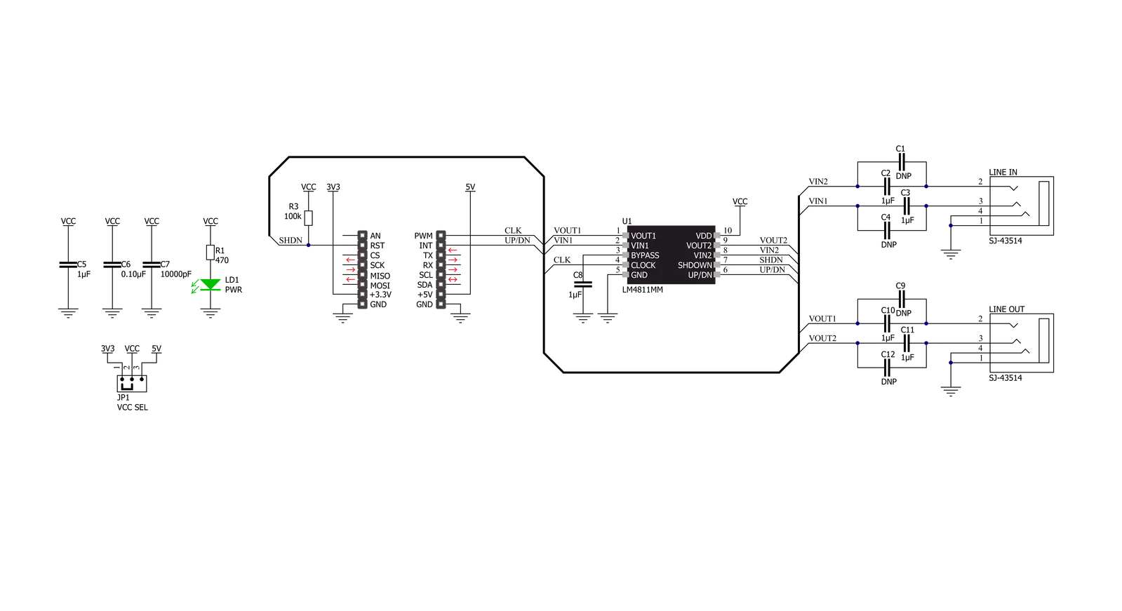
Headphone AMP Click is based on the LM4811, a stereo, analog input headphone amplifier with digital volume control from Texas Instruments. This headphone amplifier is designed to provide high-quality output power using few external components and does not require bootstrap capacitors or snubber networks for stability improvement. The maximum power delivered by the LM4811 headphone amplifier is 105mW per channel into 16Ω and 70mW with 16Ω load impedance. Other prominent features of the ML4811 also include digital volume control, "Click and Pop" suppression circuitry, and a low shutdown current of 0.3μA. This Click board™ communicates with MCU using several GPIO pins.
The signals from the CLK and U/D pins routed to the PWM and INT pins of the mikroBUS™ socket control the LM4811's gain. The gain will increase or decrease by a 3dB step depending on the logic voltage level applied to the U/D pin at each rising edge of the CLK signal. A logic high voltage level applied to the U/D pin causes the gain to increase by 3dB at each rising edge of the CLK signal and vice versa. The amplifier's gain is set to a default value of 0dB upon the devices' Power-On features. Sixteen discrete gain settings range from +12dB maximum to −33dB minimum. The unity-gain stable LM4811 also features an externally controlled, active-high, micro-power consumption Shutdown mode, available on the RST pin of the
mikroBUS™ socket, to reduce power consumption while not in use. However, when coming out of Shutdown mode, the LM4811 will revert to its previous gain setting. Alongside all these features, the LM4811 also has an internal thermal shutdown protection mechanism. This Click board™ can operate with either 3.3V or 5V logic voltage levels selected via the VCC SEL jumper. This way, both 3.3V and 5V capable MCUs can use the communication lines properly. Also, this Click board™ comes equipped with a library containing easy-to-use functions and an example code that can be used as a reference for further development.


Features overview
Development board
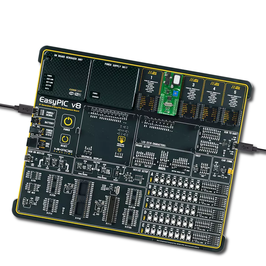
Fusion for TIVA v8 is a development board specially designed for the needs of rapid development of embedded applications. It supports a wide range of microcontrollers, such as different 32-bit ARM® Cortex®-M based MCUs from Texas Instruments, regardless of their number of pins, and a broad set of unique functions, such as the first-ever embedded debugger/programmer over a WiFi network. The development board is well organized and designed so that the end-user has all the necessary elements, such as switches, buttons, indicators, connectors, and others, in one place. Thanks to innovative manufacturing technology, Fusion for TIVA v8 provides a fluid and immersive working experience, allowing access
anywhere and under any circumstances at any time. Each part of the Fusion for TIVA v8 development board contains the components necessary for the most efficient operation of the same board. An advanced integrated CODEGRIP programmer/debugger module offers many valuable programming/debugging options, including support for JTAG, SWD, and SWO Trace (Single Wire Output)), and seamless integration with the Mikroe software environment. Besides, it also includes a clean and regulated power supply module for the development board. It can use a wide range of external power sources, including a battery, an external 12V power supply, and a power source via the USB Type-C (USB-C) connector.
Communication options such as USB-UART, USB HOST/DEVICE, CAN (on the MCU card, if supported), and Ethernet is also included. In addition, it also has the well-established mikroBUS™ standard, a standardized socket for the MCU card (SiBRAIN standard), and two display options for the TFT board line of products and character-based LCD. Fusion for TIVA v8 is an integral part of the Mikroe ecosystem for rapid development. Natively supported by Mikroe software tools, it covers many aspects of prototyping and development thanks to a considerable number of different Click boards™ (over a thousand boards), the number of which is growing every day.

Microcontroller Overview
MCU Card / MCU

Type
8th Generation
Architecture
ARM Cortex-M4
MCU Memory (KB)
1024
Silicon Vendor
Texas Instruments
Pin count
128
RAM (Bytes)
262144
You complete me!
Accessories
These standard small stereo earphones offer a high-quality listening experience with their top-notch stereo cable and connector. Designed for universal compatibility, they effortlessly connect to all MIKROE mikromedia and multimedia boards, making them an ideal choice for your electronic projects. With a rated power of 100mW, the earphones provide crisp audio across a broad frequency range from 20Hz to 20kHz. They boast a sensitivity of 100 ± 5dB and an impedance of 32Ω ± 15%, ensuring optimal sound quality. The Φ15mm speaker delivers clear and immersive audio. Cost-effective and versatile, these earphones are perfect for testing your prototype devices, offering an affordable and reliable audio solution to complement your projects.

Used MCU Pins
mikroBUS™ mapper
Take a closer look
Click board™ Schematic
Step by step
Project assembly

Start by selecting your development board and Click board™. Begin with the Fusion for Tiva v8 as your development board.


Track your results in real time
Application Output
1. Application Output - In Debug mode, the 'Application Output' window enables real-time data monitoring, offering direct insight into execution results. Ensure proper data display by configuring the environment correctly using the provided tutorial.

2. UART Terminal - Use the UART Terminal to monitor data transmission via a USB to UART converter, allowing direct communication between the Click board™ and your development system. Configure the baud rate and other serial settings according to your project's requirements to ensure proper functionality. For step-by-step setup instructions, refer to the provided tutorial.

3. Plot Output - The Plot feature offers a powerful way to visualize real-time sensor data, enabling trend analysis, debugging, and comparison of multiple data points. To set it up correctly, follow the provided tutorial, which includes a step-by-step example of using the Plot feature to display Click board™ readings. To use the Plot feature in your code, use the function: plot(*insert_graph_name*, variable_name);. This is a general format, and it is up to the user to replace 'insert_graph_name' with the actual graph name and 'variable_name' with the parameter to be displayed.

Software Support
Library Description
This library contains API for Headphone AMP Click driver.
Key functions:
headphoneamp_set_sound_volume- Headphone AMP set sound volume functionheadphoneamp_volume_up- Headphone AMP set sound volume up functionheadphoneamp_volume_down- Headphone AMP set sound volume down function
Open Source
Code example
The complete application code and a ready-to-use project are available through the NECTO Studio Package Manager for direct installation in the NECTO Studio. The application code can also be found on the MIKROE GitHub account.
/*!
 * @file main.c
 * @brief Headphone AMP Click Example.
 *
 * # Description
 * This library contains API for the Headphone AMP Click driver.
 * This demo application shows use of a Headphone AMP Click board™.
 *
 * The demo application is composed of two sections :
 *
 * ## Application Init
 * Initialization of GPIO module and log UART.
 * After driver initialization the app set default settings,
 * performs power-up sequence, sets a the sound volume of -12 dB.
 *
 * ## Application Task
 * This is an example that shows the use of Headphone AMP Click board™.
 * The app performs circles the volume from -12 dB to 3 dB back and forth,
 * increase/decrement by 3dB.
 * Results are being sent to the Usart Terminal where you can track their changes.
 *
 * @author Nenad Filipovic
 *
 */

#include "board.h"
#include "log.h"
#include "headphoneamp.h"

static headphoneamp_t headphoneamp;   /**< Headphone AMP Click driver object. */
static log_t logger;                  /**< Logger object. */

void application_init ( void )
{
    log_cfg_t log_cfg;                    /**< Logger config object. */
    headphoneamp_cfg_t headphoneamp_cfg;  /**< Click config object. */

    /**
     * Logger initialization.
     * Default baud rate: 115200
     * Default log level: LOG_LEVEL_DEBUG
     * @note If USB_UART_RX and USB_UART_TX
     * are defined as HAL_PIN_NC, you will
     * need to define them manually for log to work.
     * See @b LOG_MAP_USB_UART macro definition for detailed explanation.
     */
    LOG_MAP_USB_UART( log_cfg );
    log_init( &logger, &log_cfg );
    log_info( &logger, " Application Init " );

    // Click initialization.

    headphoneamp_cfg_setup( &headphoneamp_cfg );
    HEADPHONEAMP_MAP_MIKROBUS( headphoneamp_cfg, MIKROBUS_1 );
    if ( headphoneamp_init( &headphoneamp, &headphoneamp_cfg ) == DIGITAL_OUT_UNSUPPORTED_PIN )
    {
        log_error( &logger, " Application Init Error. " );
        log_info( &logger, " Please, run program again... " );

        for ( ; ; );
    }
    headphoneamp_default_cfg ( &headphoneamp );
    log_info( &logger, " Application Task " );
    Delay_ms ( 100 );

    log_printf( &logger, "-------------------------\r\n" );
    log_printf( &logger, "    Performs Power-up\r\n" );
    headphoneamp_power_up( &headphoneamp );
    Delay_ms ( 100 );

    log_printf( &logger, "-------------------------\r\n" );
    log_printf( &logger, "  Set volume gain -12dB\r\n", HEADPHONEAMP_SOUND_VOLUME_NEG_12_dB );
    headphoneamp_set_sound_volume( &headphoneamp, HEADPHONEAMP_SOUND_VOLUME_NEG_12_dB );
    log_printf( &logger, "-------------------------\r\n" );
    Delay_ms ( 1000 );
    Delay_ms ( 1000 );
    Delay_ms ( 1000 );
    Delay_ms ( 1000 );
    Delay_ms ( 1000 );
}

void application_task ( void )
{
    for ( uint8_t n_cnt = 0; n_cnt < 5; n_cnt++ ) {
        log_printf( &logger, "    Turning volume up\r\n" );
        headphoneamp_volume_up ( &headphoneamp );
        Delay_ms ( 1000 );
        Delay_ms ( 1000 );
    }

    log_printf( &logger, "-------------------------\r\n" );
    Delay_ms ( 1000 );
    Delay_ms ( 1000 );
    Delay_ms ( 1000 );
    Delay_ms ( 1000 );
    Delay_ms ( 1000 );

    for ( uint8_t n_cnt = 0; n_cnt < 5; n_cnt++ ) {
        log_printf( &logger, "   Turning volume down\r\n" );
        headphoneamp_volume_down ( &headphoneamp );
        Delay_ms ( 1000 );
        Delay_ms ( 1000 );
    }

    log_printf( &logger, "-------------------------\r\n" );
    Delay_ms ( 1000 );
    Delay_ms ( 1000 );
    Delay_ms ( 1000 );
    Delay_ms ( 1000 );
    Delay_ms ( 1000 );
}

int main ( void )
{
    /* Do not remove this line or clock might not be set correctly. */
    #ifdef PREINIT_SUPPORTED
    preinit();
    #endif

    application_init( );

    for ( ; ; )
    {
        application_task( );
    }

    return 0;
}

// ------------------------------------------------------------------------ END