Monitor and control pressure differentials with ease using LMIS025B and STM32F207ZG
Digital excellence in pressure sensing

Published Oct 14, 2023
Click board™
VAV Press Click
Dev. board
UNI-DS v8
Compiler
NECTO Studio
MCU
STM32F207ZG
Our digital differential pressure sensor is engineered to provide precise and reliable readings for a wide range of applications, from industrial automation to environmental monitoring
A
A
Hardware Overview
How does it work?
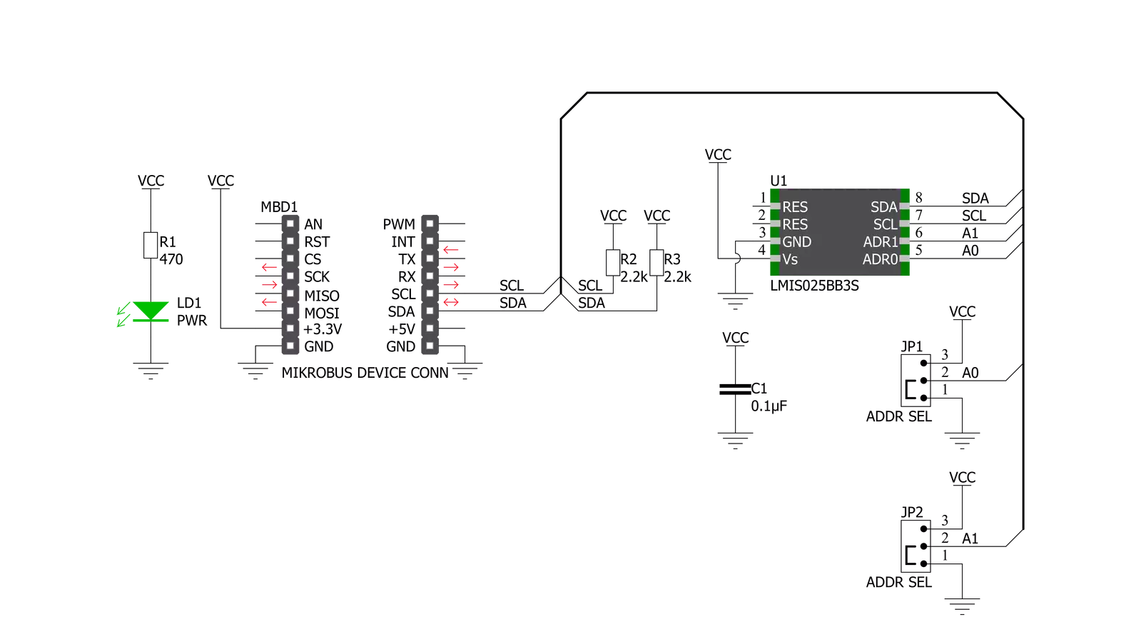
VAV Press Click is based on the LMIS025B, a low differential pressure sensor from TE Connectivity that offers a digital output for reading pressure over the specified pressure span. The innovative LMI technology features superior sensitivity, especially for ultra-low pressures ranging from 0 to 25Pa / 0 to 0.25mbar (0.1 in H2O). It is based on thermal flow measurement of gas through a micro-flow channel integrated within the sensor chip. The extremely low gas flow through the sensor ensures high immunity to dust contamination, humidity, and long tubing compared to other flow-based pressure sensors,
including the outstanding long-term stability, precision with patented real-time offset compensation, and linearization techniques. The LMIS025B offers two modes of operation: Continuous mode with a 5ms sampling time, which provides a near-continuous stream of pressure data, and low-power mode with a 400μA Standby current which wakes the device from Sleep to serve pressure data “on-demand”. The first measurement in either mode is available after a warm-up and conversion sequence, which takes approximately 25 ms. VAV Press Click communicates with MCU using the standard I2C
2-Wire interface, offering linearized digital output through a 16-bit sigma-delta A/D conversion. Besides, it also allows the choice of the least significant bit of its I2C slave address by positioning the SMD jumper labeled as ADDR SEL to an appropriate position marked as 0 and 1. This Click board™ can be operated only with a 3.3V logic voltage level. The board must perform appropriate logic voltage level conversion before using MCUs with different logic levels. Also, it comes equipped with a library containing functions and an example code that can be used as a reference for further development.


Features overview
Development board
UNI-DS v8 is a development board specially designed for the needs of rapid development of embedded applications. It supports a wide range of microcontrollers, such as different STM32, Kinetis, TIVA, CEC, MSP, PIC, dsPIC, PIC32, and AVR MCUs regardless of their number of pins, and a broad set of unique functions, such as the first-ever embedded debugger/programmer over WiFi. The development board is well organized and designed so that the end-user has all the necessary elements, such as switches, buttons, indicators, connectors, and others, in one place. Thanks to innovative manufacturing technology, UNI-DS v8 provides a fluid and immersive working experience, allowing access anywhere and under any
circumstances at any time. Each part of the UNI-DS v8 development board contains the components necessary for the most efficient operation of the same board. An advanced integrated CODEGRIP programmer/debugger module offers many valuable programming/debugging options, including support for JTAG, SWD, and SWO Trace (Single Wire Output)), and seamless integration with the Mikroe software environment. Besides, it also includes a clean and regulated power supply module for the development board. It can use a wide range of external power sources, including a battery, an external 12V power supply, and a power source via the USB Type-C (USB-C) connector. Communication options such as USB-UART, USB
HOST/DEVICE, CAN (on the MCU card, if supported), and Ethernet is also included. In addition, it also has the well-established mikroBUS™ standard, a standardized socket for the MCU card (SiBRAIN standard), and two display options for the TFT board line of products and character-based LCD. UNI-DS v8 is an integral part of the Mikroe ecosystem for rapid development. Natively supported by Mikroe software tools, it covers many aspects of prototyping and development thanks to a considerable number of different Click boards™ (over a thousand boards), the number of which is growing every day.

Microcontroller Overview
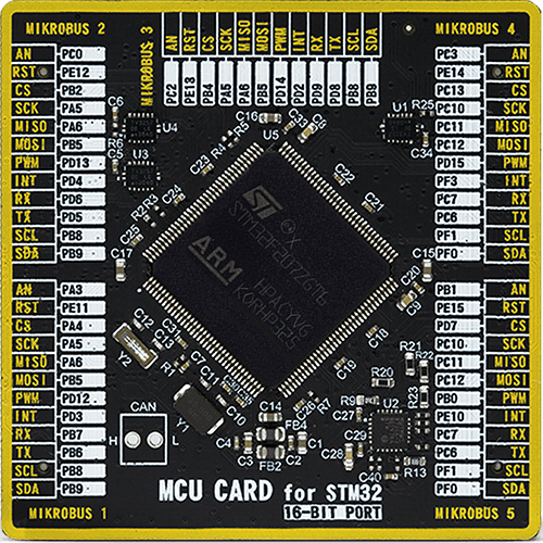
MCU Card / MCU
Type
8th Generation
Architecture
ARM Cortex-M3
MCU Memory (KB)
1024
Silicon Vendor
STMicroelectronics
Pin count
144
RAM (Bytes)
131072
Used MCU Pins
mikroBUS™ mapper
Take a closer look
Click board™ Schematic
Step by step
Project assembly

Start by selecting your development board and Click board™. Begin with the UNI-DS v8 as your development board.


Track your results in real time
Application Output
1. Application Output - In Debug mode, the 'Application Output' window enables real-time data monitoring, offering direct insight into execution results. Ensure proper data display by configuring the environment correctly using the provided tutorial.

2. UART Terminal - Use the UART Terminal to monitor data transmission via a USB to UART converter, allowing direct communication between the Click board™ and your development system. Configure the baud rate and other serial settings according to your project's requirements to ensure proper functionality. For step-by-step setup instructions, refer to the provided tutorial.

3. Plot Output - The Plot feature offers a powerful way to visualize real-time sensor data, enabling trend analysis, debugging, and comparison of multiple data points. To set it up correctly, follow the provided tutorial, which includes a step-by-step example of using the Plot feature to display Click board™ readings. To use the Plot feature in your code, use the function: plot(*insert_graph_name*, variable_name);. This is a general format, and it is up to the user to replace 'insert_graph_name' with the actual graph name and 'variable_name' with the parameter to be displayed.

Software Support
Library Description
This library contains API for VAV Press Click driver.
Key functions:
vavpress_set_default_sensor_param- VAV Press set default sensor parameter functionvavpress_get_dif_press_and_temp- VAV Press get differential pressure and temperature functionvavpress_retrieve_electronic_signature- VAV Press retrieve electronic signature function
Open Source
Code example
The complete application code and a ready-to-use project are available through the NECTO Studio Package Manager for direct installation in the NECTO Studio. The application code can also be found on the MIKROE GitHub account.
/*!
* @file main.c
* @brief VavPress Click example
*
* # Description
* This library contains API for the Vav Press Click driver.
* This demo application shows an example of
* differential pressure and temperature measurement.
*
* The demo application is composed of two sections :
*
* ## Application Init
* Initialization of I2C module and log UART.
* After driver initialization and default settings,
* the app display retrieve the electronic signature
* and set the sensor parameters data.
*
* ## Application Task
* This is an example that shows the use of a Vav Press Click board™.
* Logs pressure difference value [ Pa ] and temperature [ degree Celsius ] value.
* Results are being sent to the Usart Terminal where you can track their changes.
*
*
* @author Nenad Filipovic
*
*/
#include "board.h"
#include "log.h"
#include "vavpress.h"
static vavpress_t vavpress;
static log_t logger;
static float diff_press;
static float temperature;
vavpress_el_signature_data_t el_signature_data;
vavpress_sensor_param_data_t param_data;
void application_init ( void ) {
log_cfg_t log_cfg; /**< Logger config object. */
vavpress_cfg_t vavpress_cfg; /**< Click config object. */
/**
* Logger initialization.
* Default baud rate: 115200
* Default log level: LOG_LEVEL_DEBUG
* @note If USB_UART_RX and USB_UART_TX
* are defined as HAL_PIN_NC, you will
* need to define them manually for log to work.
* See @b LOG_MAP_USB_UART macro definition for detailed explanation.
*/
LOG_MAP_USB_UART( log_cfg );
log_init( &logger, &log_cfg );
log_printf( &logger, "\r\n" );
log_info( &logger, " Application Init " );
// Click initialization.
vavpress_cfg_setup( &vavpress_cfg );
VAVPRESS_MAP_MIKROBUS( vavpress_cfg, MIKROBUS_1 );
err_t init_flag = vavpress_init( &vavpress, &vavpress_cfg );
if ( init_flag == I2C_MASTER_ERROR ) {
log_error( &logger, " Application Init Error. " );
log_info( &logger, " Please, run program again... " );
for ( ; ; );
}
vavpress_default_cfg ( &vavpress );
log_info( &logger, " Application Task " );
Delay_ms ( 100 );
vavpress_retrieve_electronic_signature( &vavpress, &el_signature_data );
Delay_ms ( 100 );
log_printf( &logger, "--------------------------------\r\n" );
log_printf( &logger, " Firmware Version : %.3f \r\n", el_signature_data.firmware_version );
log_printf( &logger, " Pressure Range : %d Pa \r\n", el_signature_data.pressure_range );
log_printf( &logger, " Part # : %.11s \r\n", el_signature_data.part_number );
log_printf( &logger, " Lot # : %.7s \r\n", el_signature_data.lot_number );
log_printf( &logger, " Output Type : %c \r\n", el_signature_data.output_type );
log_printf( &logger, " Scale Factor : %d \r\n", el_signature_data.scale_factor );
log_printf( &logger, " Calibration ID : %.2s \r\n", el_signature_data.calibration_id );
log_printf( &logger, " Week number : %d \r\n", el_signature_data.week_number );
log_printf( &logger, " Year number : %d \r\n", el_signature_data.year_number );
log_printf( &logger, " Sequence number : %d \r\n", el_signature_data.sequence_number );
log_printf( &logger, "--------------------------------\r\n" );
Delay_ms ( 1000 );
Delay_ms ( 1000 );
param_data.scale_factor_temp = 72;
param_data.scale_factor_press = el_signature_data.scale_factor;
param_data.readout_at_known_temperature = 50;
param_data.known_temperature_c = 24.0;
Delay_ms ( 100 );
}
void application_task ( void ) {
err_t error_flag = vavpress_get_dif_press_and_temp( &vavpress, ¶m_data, &diff_press, &temperature );
if ( error_flag == VAVPRESS_OK ) {
log_printf( &logger, " Diff. Pressure : %.4f Pa\r\n", diff_press );
log_printf( &logger, " Temperature : %.4f C\r\n", temperature );
log_printf( &logger, "--------------------------------\r\n" );
Delay_ms ( 1000 );
Delay_ms ( 1000 );
} else {
log_error( &logger, " Communcation Error. " );
log_info( &logger, " Please, run program again... " );
for ( ; ; );
}
}
int main ( void )
{
/* Do not remove this line or clock might not be set correctly. */
#ifdef PREINIT_SUPPORTED
preinit();
#endif
application_init( );
for ( ; ; )
{
application_task( );
}
return 0;
}
// ------------------------------------------------------------------------ END


