Explore the endless potential of magnet rotation with MA700 and TM4C129ENCPDT
Angles in action: Innovate with magnet rotation sensing

Published Sep 15, 2023
Click board™
Angle 2 Click
Dev. board
Fusion for Tiva v8
Compiler
NECTO Studio
MCU
TM4C129ENCPDT
Discover the art of magnet tilting with our innovative solution, enabling you to capture the subtleties of magnet rotation and redefine your creative possibilities.
A
A
Hardware Overview
How does it work?
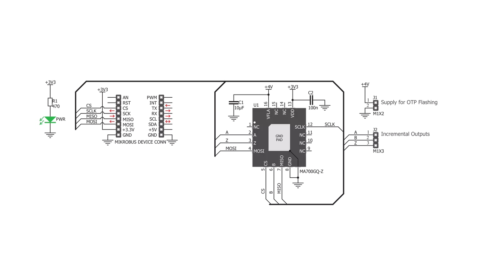
Angle 2 Click is based on the MA700, an angular sensor for position control with side-shaft positioning capability, produced by Monolithic Power Systems (MPS). This IC has a set of features, critical for high-speed angular position sensing applications: it utilizes the Spinaxis frontend that allows very fast data output rates up to 500kHz, and a very low-latency data output, down to 3 µs, even when using the data filtering and conditioning options. This makes it suitable for measuring the angle of the motor shaft in various high-speed applications, such as BLDC motor applications. It can be used at speeds up to 100,000 RPM, still retaining its accuracy. The magnetic field is only sensed along the horizontal (XZ) plane by utilizing an array of aligned Hall sensors. This allows sampling of the absolute angular position of a diametrically magnetized cylinder, typically attached at the end of the rotor shaft. Unlike some other methods, the Spinaxis does not require heavy mathematical calculations, as it is based on the phase detection, directly digitizing the magnetic field direction. This is the key to an extremely low output latency of 3µs. This also allows very accurate angular position reading, as the actual physical angle coincidences with the 11-bit data available at the output, due to practically no conversion delay. The Spinaxis
frontend also allows off-axis placement of the permanent magnet, as the MA700 features built-in linearization for the side-shaft mounting in a form of an offset register. This relaxes the mechanical demands of the user application. The incremental quadrature encoder function uses three output pins: A, B, and Z. The A signal pulses 256 times during a full revolution. The B signal is shifted by a quarter of the pulse period, depending on the direction of the rotation. The application can use this fact to determine the direction of the rotation. The Z signal pulses once per 360°. The pulses on A and B outputs are affected by jitter, which can cause the output to be inconsistent if used at speeds over 30,000 RPM. For high-speed applications, using the SPI interface is recommended. The A, B, and Z pins of the MA700 IC are routed to a standard, 2.54 mm (0.1 inches) pitch 1x3 header, mounted on the Angle 2 click, so it can be easily accessed by an external application. The MA700 also features the one-time programmable (OTP) memory, which allows the working parameters of the IC to be stored as the default values. This allows a lot of flexibility for a project design since the factory pre-flashed default values might not always fit the requirements of the specific application. A typical example might be the zero position configuration:
if the sensor must be fixed to a certain angle which has to be the start position for the angle counting (the zero angle), the user application would have to internally re-calculate values to compensate, introducing more latency. The ability to define own default settings is certainly a useful option. However, flashing the OTP memory is a sensitive process, as there is very little room for an error (being one-time programmable). The datasheet of the MA700 offers a detailed guide for flashing the OTP, while Angle 2 click offers an external power supply (PSU) connector, implemented as the standard 2.54mm 1x2 header. The OTP flashing requires a separate PSU of 4V to be used. The SPI communication consists of the read/write (R/W) command, an address of the register, and the data. The R/W command and the address are two 4-bit values, while the data is a single 8-bit value. The MA700 datasheet contains the detailed information on all the commands, however, Angle 2 click comes with the library that contains very simplified angle reading functions, as well as the functions used for an easy configuring of the Angle 2 click. The MA700 SPI pins are routed to the respective pins of the mikroBUS™, allowing easy and reliable interfacing with the host MCU.


Features overview
Development board
Fusion for TIVA v8 is a development board specially designed for the needs of rapid development of embedded applications. It supports a wide range of microcontrollers, such as different 32-bit ARM® Cortex®-M based MCUs from Texas Instruments, regardless of their number of pins, and a broad set of unique functions, such as the first-ever embedded debugger/programmer over a WiFi network. The development board is well organized and designed so that the end-user has all the necessary elements, such as switches, buttons, indicators, connectors, and others, in one place. Thanks to innovative manufacturing technology, Fusion for TIVA v8 provides a fluid and immersive working experience, allowing access
anywhere and under any circumstances at any time. Each part of the Fusion for TIVA v8 development board contains the components necessary for the most efficient operation of the same board. An advanced integrated CODEGRIP programmer/debugger module offers many valuable programming/debugging options, including support for JTAG, SWD, and SWO Trace (Single Wire Output)), and seamless integration with the Mikroe software environment. Besides, it also includes a clean and regulated power supply module for the development board. It can use a wide range of external power sources, including a battery, an external 12V power supply, and a power source via the USB Type-C (USB-C) connector.
Communication options such as USB-UART, USB HOST/DEVICE, CAN (on the MCU card, if supported), and Ethernet is also included. In addition, it also has the well-established mikroBUS™ standard, a standardized socket for the MCU card (SiBRAIN standard), and two display options for the TFT board line of products and character-based LCD. Fusion for TIVA v8 is an integral part of the Mikroe ecosystem for rapid development. Natively supported by Mikroe software tools, it covers many aspects of prototyping and development thanks to a considerable number of different Click boards™ (over a thousand boards), the number of which is growing every day.

Microcontroller Overview
MCU Card / MCU

Type
8th Generation
Architecture
ARM Cortex-M4
MCU Memory (KB)
1024
Silicon Vendor
Texas Instruments
Pin count
128
RAM (Bytes)
262144
Used MCU Pins
mikroBUS™ mapper
Take a closer look
Click board™ Schematic
Step by step
Project assembly

Start by selecting your development board and Click board™. Begin with the Fusion for Tiva v8 as your development board.


Software Support
Library Description
This library contains API for Angle 2 Click driver.
Key functions:
angle2_get_angle- This function reads angle data from the click moduleangle2_get_angle_with_time_index- This function reads angle and time index data from the click moduleangle2_set_zero_scale- This function sets the zero scale value.
Open Source
Code example
The complete application code and a ready-to-use project are available through the NECTO Studio Package Manager for direct installation in the NECTO Studio. The application code can also be found on the MIKROE GitHub account.
/*!
 * \file
 * \brief Angle2 Click example
 *
 * # Description
 * This example showcases how to configure and use the Angle 2 Click. This Click senses
 * the magnetic field along the horizontal plane using an array of Hal effect sensors.
 * The module uses advanced Spinaxis technology based on a direct angle sampling app-
 * roach in order to provide reliable data quickly.
 *
 * The demo application is composed of two sections :
 *
 * ## Application Init
 * This function initializes and configures the Click and logger modules. Additional con-
 * figuring is done in the default_cfg(...) function.
 *
 * ## Application Task
 * This function reads angle data from the Click module and displays that data using the
 * UART console every 200 miliseconds.
 *
 * \author MikroE Team
 *
 */
// ------------------------------------------------------------------- INCLUDES

#include "board.h"
#include "log.h"
#include "angle2.h"

// ------------------------------------------------------------------ VARIABLES

static angle2_t angle2;
static log_t logger;

// ------------------------------------------------------ APPLICATION FUNCTIONS

void application_init ( )
{
    log_cfg_t log_cfg;
    angle2_cfg_t cfg;

    /**
     * Logger initialization.
     * Default baud rate: 115200
     * Default log level: LOG_LEVEL_DEBUG
     * @note If USB_UART_RX and USB_UART_TX
     * are defined as HAL_PIN_NC, you will
     * need to define them manually for log to work.
     * See @b LOG_MAP_USB_UART macro definition for detailed explanation.
     */
    LOG_MAP_USB_UART( log_cfg );
    log_init( &logger, &log_cfg );
    log_info( &logger, "---- Application Init ----" );
    Delay_ms ( 100 );

    //  Click initialization.

    angle2_cfg_setup( &cfg );
    ANGLE2_MAP_MIKROBUS( cfg, MIKROBUS_1 );
    angle2_init( &angle2, &cfg );

    Delay_ms ( 300 );
    angle2_default_cfg( &angle2 );
    Delay_ms ( 200 );

    log_printf( &logger, " * Angle 2 initialized * \r\n" );
}

void application_task ( )
{
    double angle;

    angle = angle2_get_angle( &angle2 );

    log_printf( &logger, " Angle: %.2f deg\r\n", angle );

    Delay_ms ( 200 );
}

int main ( void )
{
    /* Do not remove this line or clock might not be set correctly. */
    #ifdef PREINIT_SUPPORTED
    preinit();
    #endif

    application_init( );

    for ( ; ; )
    {
        application_task( );
    }

    return 0;
}

// ------------------------------------------------------------------------ END


