Provide accurate heading information for map rotation and user orientation with the AK09919 and PIC32MZ2048EFM100
3-axis magnetometer suitable for custom pedestrian navigation systems or map heading applications

Published Jun 27, 2024
Click board™
Compass 8 Click
Dev. board
Curiosity PIC32 MZ EF
Compiler
NECTO Studio
MCU
PIC32MZ2048EFM100
Transform your project into a precise digital compass ideal for applications where orientation and direction are crucial
A
A
Hardware Overview
How does it work?
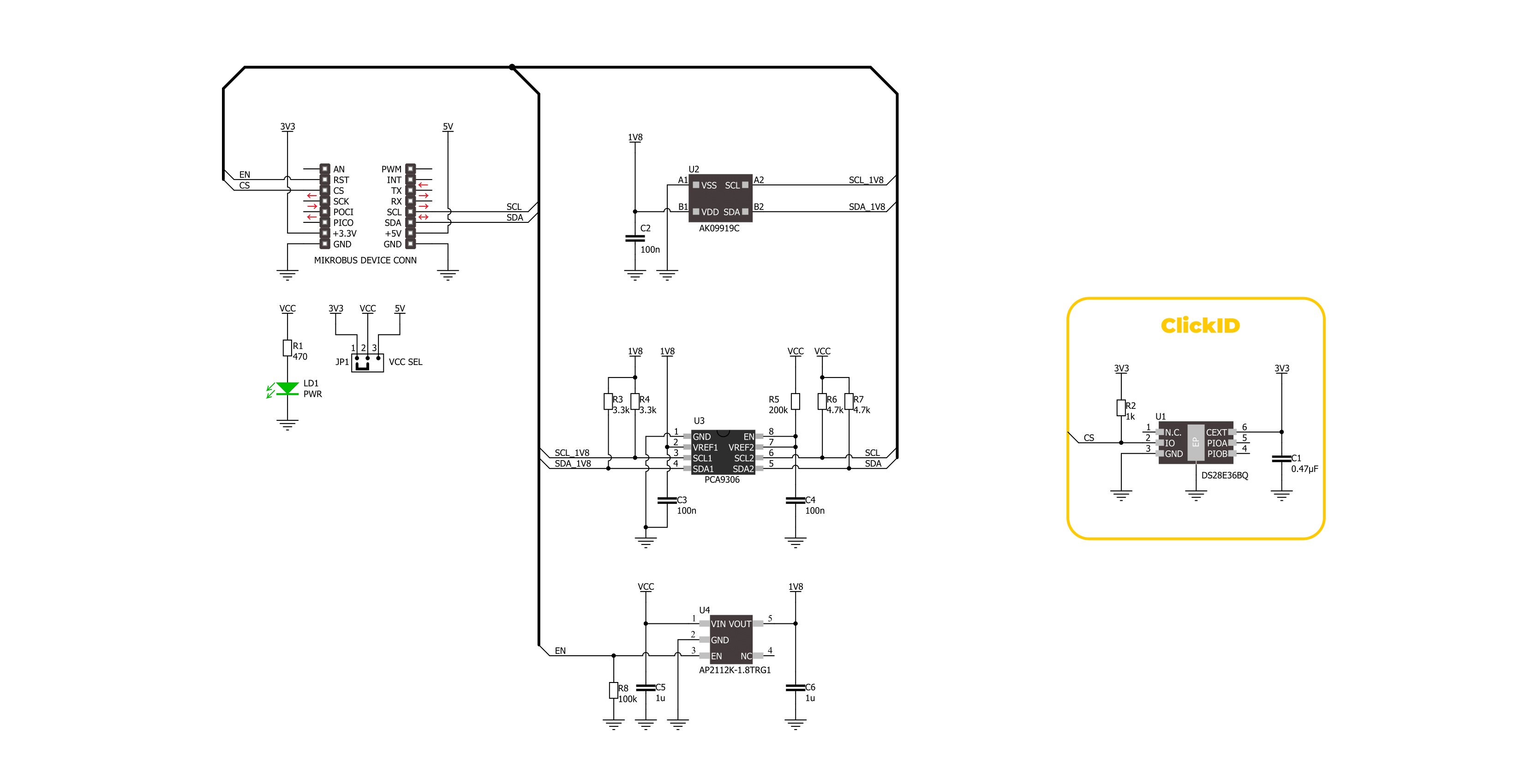
Compass 8 Click is based on the AK09919, a 3-axis electronic compass IC from AKM Semiconductor designed for precise compass applications. The AK09919 uses high-sensitivity Hall sensor technology, with a typical sensitivity of 0.15µT/LSB, to detect terrestrial magnetism across the X, Y, and Z axes. It integrates magnetic sensors, a sensor driving circuit, a signal amplifier chain, and an arithmetic circuit for signal processing. Key features of the AK09919 also include multiple operational modes, such as Power-down, single measurement, continuous measurement, and self-test. The Power-down mode conserves energy when the device is not in use, while the single measurement mode allows for precise readings on demand. The continuous measurement mode provides ongoing data for real-time applications, and the self-test mode ensures the sensor functions correctly. Additionally, the magnetic sensor overflow monitor function manages overflow conditions in the magnetic
sensors, ensuring accurate readings even in strong magnetic fields. The AK09919 also features a built-in oscillator for a stable internal clock source, maintaining consistent performance and timing accuracy. The Power On Reset circuit ensures proper initialization upon power-up, preventing erroneous readings. The self-test function, which uses an internal magnetic source, verifies the sensor's accuracy and functionality without external equipment. The built-in magnetic sensitivity adjustment circuit optimizes performance across different environments and applications. Moreover, the 16-sample FIFO data buffer allows efficient data handling, reducing the need for frequent processor intervention. This board is ideal for continuous data acquisition in map heading and pedestrian navigation systems applications. Compass 8 Click communicates with MCU using the standard I2C 2-Wire interface with a maximum clock frequency of 400kHz, fully adjustable through software registers. The AK09919 does not require a
specific Power-Up sequence but requires a voltage of 1.8V for its interface and logic part to work correctly. Therefore, a small regulating LDO, the AP2112, is used to provide a 1.8V out of mikroBUS™ power rails. This regulator can be activated via the EN pin of the mikroBUS™ socket, providing, at the same time, device enable function. Since the sensor for operation requires a power supply of 1.8V, this Click board™ also features the PCA9306 voltage-level translator, allowing the AK09919 to work with 3.3V and 5V MCU properly. This Click board™ can operate with either 3.3V or 5V logic voltage levels selected via the VCC SEL jumper. This way, both 3.3V and 5V capable MCUs can use the communication lines properly. Also, this Click board™ comes equipped with a library containing easy-to-use functions and an example code that can be used as a reference for further development.

Features overview
Development board
Curiosity PIC32 MZ EF development board is a fully integrated 32-bit development platform featuring the high-performance PIC32MZ EF Series (PIC32MZ2048EFM) that has a 2MB Flash, 512KB RAM, integrated FPU, Crypto accelerator, and excellent connectivity options. It includes an integrated programmer and debugger, requiring no additional hardware. Users can expand
functionality through MIKROE mikroBUS™ Click™ adapter boards, add Ethernet connectivity with the Microchip PHY daughter board, add WiFi connectivity capability using the Microchip expansions boards, and add audio input and output capability with Microchip audio daughter boards. These boards are fully integrated into PIC32’s powerful software framework, MPLAB Harmony,
which provides a flexible and modular interface to application development a rich set of inter-operable software stacks (TCP-IP, USB), and easy-to-use features. The Curiosity PIC32 MZ EF development board offers expansion capabilities making it an excellent choice for a rapid prototyping board in Connectivity, IOT, and general-purpose applications.

Microcontroller Overview
MCU Card / MCU

Architecture
PIC32
MCU Memory (KB)
2048
Silicon Vendor
Microchip
Pin count
100
RAM (Bytes)
524288
Used MCU Pins
mikroBUS™ mapper
Take a closer look
Click board™ Schematic
Step by step
Project assembly

Start by selecting your development board and Click board™. Begin with the Curiosity PIC32 MZ EF as your development board.


Track your results in real time
Application Output
1. Application Output - In Debug mode, the 'Application Output' window enables real-time data monitoring, offering direct insight into execution results. Ensure proper data display by configuring the environment correctly using the provided tutorial.

2. UART Terminal - Use the UART Terminal to monitor data transmission via a USB to UART converter, allowing direct communication between the Click board™ and your development system. Configure the baud rate and other serial settings according to your project's requirements to ensure proper functionality. For step-by-step setup instructions, refer to the provided tutorial.

3. Plot Output - The Plot feature offers a powerful way to visualize real-time sensor data, enabling trend analysis, debugging, and comparison of multiple data points. To set it up correctly, follow the provided tutorial, which includes a step-by-step example of using the Plot feature to display Click board™ readings. To use the Plot feature in your code, use the function: plot(*insert_graph_name*, variable_name);. This is a general format, and it is up to the user to replace 'insert_graph_name' with the actual graph name and 'variable_name' with the parameter to be displayed.

Software Support
Library Description
This library contains API for Compass 8 Click driver.
Key functions:
compass8_get_magnetic_data- This function reads the raw magnetic sensor measurement data and calculates magnetic flux density [microTesla] using the I2C serial interface.compass8_set_operation_mode- This function sets the desired sensor operation mode by using the I2C serial interface.compass8_sw_reset- This function performs software reset by using the I2C serial interface.
Open Source
Code example
The complete application code and a ready-to-use project are available through the NECTO Studio Package Manager for direct installation in the NECTO Studio. The application code can also be found on the MIKROE GitHub account.
/*!
 * @file main.c
 * @brief Compass 8 Click example
 *
 * # Description
 * This library contains API for the Compass 8 Click driver.
 * The library initializes and defines the I2C drivers to
 * write and read data from registers, as well as the default
 * configuration for reading measurement data.
 *
 * The demo application is composed of two sections :
 *
 * ## Application Init
 * The initialization of the I2C module, log UART, and additional pins.
 * After the driver init, the app executes a default configuration.
 *
 * ## Application Task
 * This example demonstrates the use of the Compass 8 Click board.
 * Measures and displays magnetic flux density in microtesla (uT) for X-axis, Y-axis, and Z-axis.
 * Results are being sent to the UART Terminal, where you can track their changes.
 *
 * @author Nenad Filipovic
 *
 */

#include "board.h"
#include "log.h"
#include "compass8.h"

static compass8_t compass8;
static log_t logger;

void application_init ( void )
{
    log_cfg_t log_cfg;  /**< Logger config object. */
    compass8_cfg_t compass8_cfg;  /**< Click config object. */

    /**
     * Logger initialization.
     * Default baud rate: 115200
     * Default log level: LOG_LEVEL_DEBUG
     * @note If USB_UART_RX and USB_UART_TX
     * are defined as HAL_PIN_NC, you will
     * need to define them manually for log to work.
     * See @b LOG_MAP_USB_UART macro definition for detailed explanation.
     */
    LOG_MAP_USB_UART( log_cfg );
    log_init( &logger, &log_cfg );
    log_info( &logger, " Application Init " );

    // Click initialization.
    compass8_cfg_setup( &compass8_cfg );
    COMPASS8_MAP_MIKROBUS( compass8_cfg, MIKROBUS_1 );
    if ( I2C_MASTER_ERROR == compass8_init( &compass8, &compass8_cfg ) )
    {
        log_error( &logger, " Communication init." );
        for ( ; ; );
    }

    if ( COMPASS8_ERROR == compass8_default_cfg ( &compass8 ) )
    {
        log_error( &logger, " Default configuration." );
        for ( ; ; );
    }

    log_info( &logger, " Application Task " );
}

void application_task ( void )
{
    compass8_axes_t axis;
    if ( COMPASS8_OK == compass8_get_magnetic_data( &compass8, &axis ) )
    {
        log_printf( &logger, " X-axis: %.2f uT\r\n", axis.x );
        log_printf( &logger, " Y-axis: %.2f uT\r\n", axis.y );
        log_printf( &logger, " Z-axis: %.2f uT\r\n", axis.z );
        log_printf( &logger,  "--------------------\r\n" );
        Delay_ms ( 100 );
    }
}

int main ( void )
{
    /* Do not remove this line or clock might not be set correctly. */
    #ifdef PREINIT_SUPPORTED
    preinit();
    #endif

    application_init( );

    for ( ; ; )
    {
        application_task( );
    }

    return 0;
}

// ------------------------------------------------------------------------ END


