Achieve real-time data exchange over extended distances with MAX1471 and TM4C129ENCPDT
Revolutionize your wireless world: Discover the power of sub-GHz RF technology!

Published Nov 09, 2023
Click board™
ISM RX Click
Dev. board
Fusion for Tiva v8
Compiler
NECTO Studio
MCU
TM4C129ENCPDT
Our sub-GHz ISM RF receiver empowers seamless long-range communication for IoT devices, bridging the gap where others fall short.
A
A
Hardware Overview
How does it work?
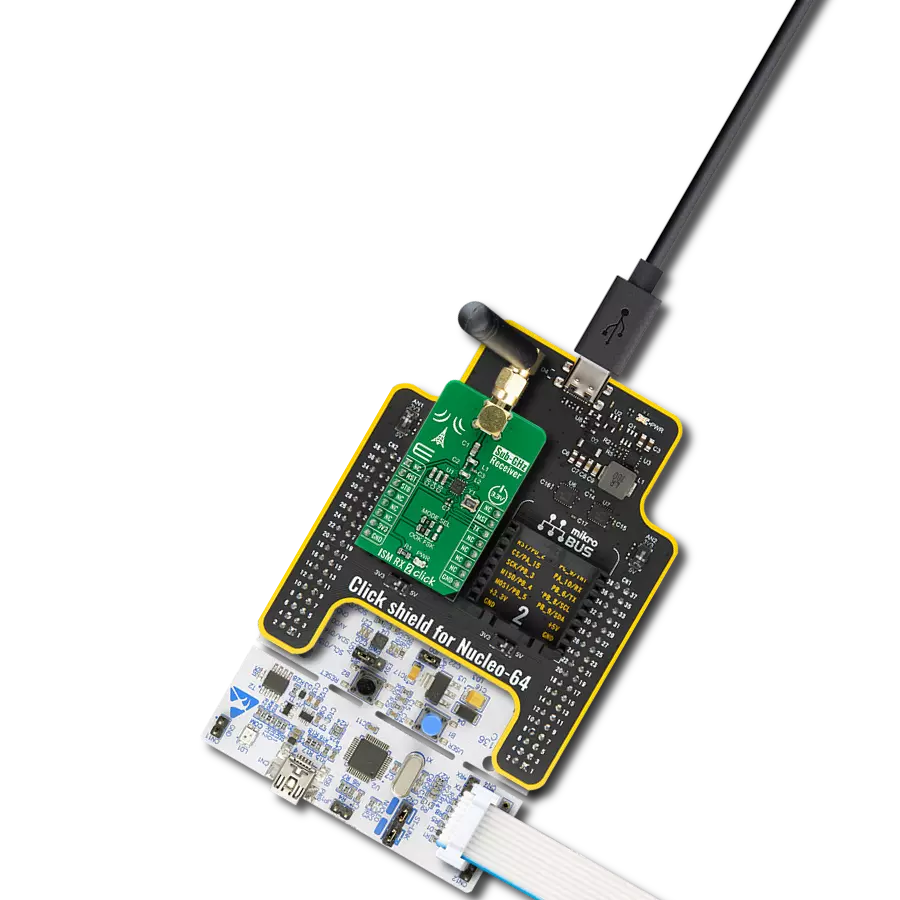
ISM RX Click is based on the MAX1471, a low-power CMOS superheterodyne receiver for ASK and FSK data without reconfiguration from Analog Devices. It includes all the active components, such as a low-noise amplifier, an image-reject mixer, a fully integrated PLL, a 10.7MHz IF limiting amplifier received-signal strength indicator, a low-noise FM demodulator, and a 3V voltage regulator. The MAX1471 can achieve data rates as high as 33kbps using Manchester Code (66kbps nonreturn to zero), depending on signal power and component selection. As mentioned, this Click board™ can receive both ASK and FSK data simultaneously. This feature of the MAX1471 can be achieved and selected with the switch labeled DMOD SEL that allows the selection between ASK and FSK data. The MAX1471 receives binary FSK or ASK
data at 433.92MHz, set based on the used components. ASK modulation uses a difference in the carrier's amplitude to represent logic 0 and logic 1 data, while the FSK uses the difference in frequency of the carrier. Differential peak-detecting data demodulators are available for FSK and ASK analog baseband data recovery. The MAX1471 consists of a discontinuous Receive mode for low-power operation, configured through a serial interface. This mode also allows self-polling, where the MAX1471 can stay in Sleep mode for as long as eight minutes and wake the system MCU, offering additional power savings. On the consumption side, it draws less than 1.1µA in Shutdown and only 7mA in Receive mode. ISM RX Click communicates with MCU using a standard SPI interface and possesses the SMA
antenna connector with an impedance of 50Ω. This Click board™ can use the appropriate antenna that Mikroe has in its offer for improved range and received signal strength. This Click board™ operates only with a 5V logic voltage from the mikroBUS™ socket. Still, the MAX1471 power supply offers the possibility of using both 3V, obtained by the NCP170 voltage regulator, and 5V logic voltage level selected via the HVIN SEL jumpers. Note that all the jumpers must be placed on the same side, or the Click board™ may become unresponsive. Also, this Click board™ comes equipped with a library containing easy-to-use functions and an example code that can be used as a reference for further development.

Features overview
Development board
Fusion for TIVA v8 is a development board specially designed for the needs of rapid development of embedded applications. It supports a wide range of microcontrollers, such as different 32-bit ARM® Cortex®-M based MCUs from Texas Instruments, regardless of their number of pins, and a broad set of unique functions, such as the first-ever embedded debugger/programmer over a WiFi network. The development board is well organized and designed so that the end-user has all the necessary elements, such as switches, buttons, indicators, connectors, and others, in one place. Thanks to innovative manufacturing technology, Fusion for TIVA v8 provides a fluid and immersive working experience, allowing access
anywhere and under any circumstances at any time. Each part of the Fusion for TIVA v8 development board contains the components necessary for the most efficient operation of the same board. An advanced integrated CODEGRIP programmer/debugger module offers many valuable programming/debugging options, including support for JTAG, SWD, and SWO Trace (Single Wire Output)), and seamless integration with the Mikroe software environment. Besides, it also includes a clean and regulated power supply module for the development board. It can use a wide range of external power sources, including a battery, an external 12V power supply, and a power source via the USB Type-C (USB-C) connector.
Communication options such as USB-UART, USB HOST/DEVICE, CAN (on the MCU card, if supported), and Ethernet is also included. In addition, it also has the well-established mikroBUS™ standard, a standardized socket for the MCU card (SiBRAIN standard), and two display options for the TFT board line of products and character-based LCD. Fusion for TIVA v8 is an integral part of the Mikroe ecosystem for rapid development. Natively supported by Mikroe software tools, it covers many aspects of prototyping and development thanks to a considerable number of different Click boards™ (over a thousand boards), the number of which is growing every day.

Microcontroller Overview
MCU Card / MCU

Type
8th Generation
Architecture
ARM Cortex-M4
MCU Memory (KB)
1024
Silicon Vendor
Texas Instruments
Pin count
128
RAM (Bytes)
262144
You complete me!
Accessories
Right angle 433MHz rubber antenna boasts a frequency range of 433MHz, ensuring optimal performance within this spectrum. With a 50Ohm impedance, it facilitates efficient signal transmission. The antenna's vertical polarization enhances signal reception in a specific orientation. Featuring a 1.5dB gain, it can improve signal strength to some extent. The antenna can handle a maximum input power of 50W, making it suitable for various applications. Its compact 50mm length minimizes spatial requirements. Equipped with an SMA male connector, it easily interfaces with compatible devices. This antenna is an adaptable solution for wireless communication needs, particularly when vertical polarization is crucial.

Used MCU Pins
mikroBUS™ mapper
Take a closer look
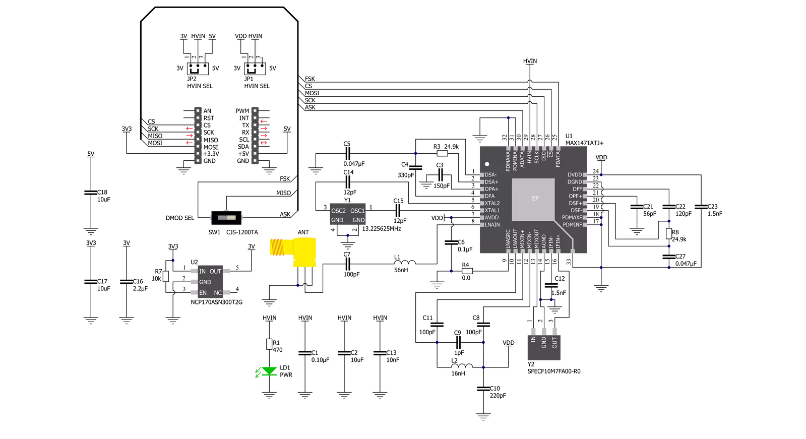
Click board™ Schematic
Step by step
Project assembly

Start by selecting your development board and Click board™. Begin with the Fusion for Tiva v8 as your development board.


Track your results in real time
Application Output
1. Application Output - In Debug mode, the 'Application Output' window enables real-time data monitoring, offering direct insight into execution results. Ensure proper data display by configuring the environment correctly using the provided tutorial.

2. UART Terminal - Use the UART Terminal to monitor data transmission via a USB to UART converter, allowing direct communication between the Click board™ and your development system. Configure the baud rate and other serial settings according to your project's requirements to ensure proper functionality. For step-by-step setup instructions, refer to the provided tutorial.

3. Plot Output - The Plot feature offers a powerful way to visualize real-time sensor data, enabling trend analysis, debugging, and comparison of multiple data points. To set it up correctly, follow the provided tutorial, which includes a step-by-step example of using the Plot feature to display Click board™ readings. To use the Plot feature in your code, use the function: plot(*insert_graph_name*, variable_name);. This is a general format, and it is up to the user to replace 'insert_graph_name' with the actual graph name and 'variable_name' with the parameter to be displayed.

Software Support
Library Description
This library contains API for ISM RX Click driver.
Key functions:
ismrx_generic_write- ISM RX data writing function.ismrx_master_reset- This sends command for resetting device.ismrx_get_data- ISM RX get miso pin state.
Open Source
Code example
The complete application code and a ready-to-use project are available through the NECTO Studio Package Manager for direct installation in the NECTO Studio. The application code can also be found on the MIKROE GitHub account.
/*!
 * @file main.c
 * @brief ISMRX Click example
 *
 * # Description
 * This application shows capability of ISM RX Click board.
 * It sets default configuration, and collects and processes
 * data from signal that received from ISM TX Click board.
 * It can collect and process data from 2 type of the signal
 * modulation( FSK and ASK ).
 *
 * The demo application is composed of two sections :
 *
 * ## Application Init
 * Initialization of log and communication, set's signal
 * modulation(FSK/ASK), recive mode(continuous/discontinuous),
 * default configuration for selected modulation, and
 * reinitializes device for receiving mode.
 *
 * ## Application Task
 * Collects samples of data from data line(MISO) when buffer
 * is full converts samples to manchester encoded data,
 * and checks for preamble(sync) data. If data is valid
 * decodes data and converts bits to valid data and logs
 * result of received decoded data.
 *
 * ## Additional Function
 * - static void clear_buffers ( void )
 * - static void wait_for_data ( void )
 * - static void man_to_hex_array ( void )
 *
 * @author Luka Filipovic
 *
 */

#include "board.h"
#include "log.h"
#include "ismrx.h"

static ismrx_t ismrx;
static log_t logger;

#define MAN_BUF_SIZE                    300
#define DATA_BUF_SIZE                   50

#define PREAMBLE_STRING                 "0101010101010101"

static uint8_t manchester_buf[ MAN_BUF_SIZE ];
static uint8_t data_buf[ DATA_BUF_SIZE ];

static uint16_t manchester_cnt          = 0;
static uint16_t data_cnt                = 0;

/**
 * @brief Clears app buffers.
 * @details This function clears application buffer and resets counters.
 * @return Nothing.
 */
static void clear_buffers ( void );

/**
 * @brief Waits for data start sequence.
 * @details This function waits for data start sequence.
 * @return Nothing.
 */
static void wait_for_data ( void );

/**
 * @brief Converts manchester_buf to data_buf hex array.
 * @details This function converts manchester_buf to data_buf hex array.
 * @return Nothing.
 */
static void man_to_hex_array ( void );

void application_init ( void )
{
    log_cfg_t log_cfg;  /**< Logger config object. */
    ismrx_cfg_t ismrx_cfg;  /**< Click config object. */

    /**
     * Logger initialization.
     * Default baud rate: 115200
     * Default log level: LOG_LEVEL_DEBUG
     * @note If USB_UART_RX and USB_UART_TX
     * are defined as HAL_PIN_NC, you will
     * need to define them manually for log to work.
     * See @b LOG_MAP_USB_UART macro definition for detailed explanation.
     */
    LOG_MAP_USB_UART( log_cfg );
    log_init( &logger, &log_cfg );
    log_info( &logger, " Application Init " );

    // Click initialization.
    ismrx_cfg_setup( &ismrx_cfg );
    ISMRX_MAP_MIKROBUS( ismrx_cfg, MIKROBUS_1 );
    if ( SPI_MASTER_ERROR == ismrx_init( &ismrx, &ismrx_cfg ) )
    {
        log_error( &logger, " Application Init Error. " );
        log_info( &logger, " Please, run program again... " );
        for ( ; ; );
    }
    Delay_ms ( 1000 );

    ismrx_master_reset( &ismrx );

    ismrx.modulation = ISMRX_MODULATION_FSK;
    ismrx.receive_mode = ISMRX_RECEIVE_MODE_RX;

    if ( ismrx_default_cfg ( &ismrx ) < 0 )
    {
        log_error( &logger, " Default configuration error. " );
        log_info( &logger, " Please, select signal modulation and/or receive mode... " );
        for ( ; ; );
    }

    if ( ismrx_task_init( &ismrx, &ismrx_cfg ) < 0 )
    {
        log_error( &logger, " Application Task Error. " );
    }

    log_info( &logger, " Application Task " );

    if ( ISMRX_RECEIVE_MODE_DRX == ismrx.receive_mode )
    {
       ismrx_start_drx( &ismrx );
    }
}

void application_task ( void )
{
    uint8_t transition = 0;

    clear_buffers ( );
    wait_for_data ( );
    Delay_50us ( );

    while ( manchester_cnt < MAN_BUF_SIZE )
    {
        transition = ismrx_get_data ( &ismrx );
        while ( transition == ismrx_get_data ( &ismrx ) );

        if ( transition )
        {
            manchester_buf[ manchester_cnt++ ] = '1';
            manchester_buf[ manchester_cnt++ ] = '0';
        }
        else
        {
            manchester_buf[ manchester_cnt++ ] = '0';
            manchester_buf[ manchester_cnt++ ] = '1';
        }
        Delay_500us ( );
        Delay_50us ( );
    }

    man_to_hex_array ( );

    for ( uint16_t byte_cnt = 0; byte_cnt < data_cnt; byte_cnt++ )
    {
        log_printf( &logger, "%.2X ", ( uint16_t ) data_buf[ byte_cnt ] );
    }

    if ( data_cnt )
    {
        log_printf( &logger, "\r\n%s\r\n", &data_buf[ 2 ] );
    }
}

int main ( void )
{
    /* Do not remove this line or clock might not be set correctly. */
    #ifdef PREINIT_SUPPORTED
    preinit();
    #endif

    application_init( );

    for ( ; ; )
    {
        application_task( );
    }

    return 0;
}

static void clear_buffers ( void )
{
    memset( manchester_buf, 0, MAN_BUF_SIZE );
    manchester_cnt = 0;
    memset( data_buf, 0, DATA_BUF_SIZE );
    data_cnt = 0;
}

static void wait_for_data ( void )
{
    uint16_t timeout_cnt = 0;
    while ( timeout_cnt < 30 )
    {
        if ( ismrx_get_data ( &ismrx ) )
        {
            timeout_cnt++;
        }
        else
        {
            timeout_cnt = 0;
        }
        Delay_50us ( );
    }
    while ( ismrx_get_data ( &ismrx ) );
}

static void man_to_hex_array ( void )
{
    uint16_t num_bytes_left = 0;
    uint16_t byte_cnt = 0;
    uint16_t bit_cnt = 0;
    uint8_t * __generic_ptr cmd_start;
    cmd_start = strstr( manchester_buf, PREAMBLE_STRING );
    memset ( data_buf, 0, sizeof ( data_buf ) );
    data_cnt = 0;
    if ( cmd_start )
    {
        num_bytes_left = ( manchester_cnt - ( cmd_start - manchester_buf ) );

        for ( byte_cnt = 0; ( ( byte_cnt < 2 ) && ( byte_cnt < DATA_BUF_SIZE ) ); byte_cnt++ )
        {
            for ( bit_cnt = 0; ( ( bit_cnt < 8 ) && ( num_bytes_left >= 2 ) ); bit_cnt++ )
            {
                if ( ( '0' == cmd_start[ byte_cnt * 16 + bit_cnt * 2 ] ) &&
                     ( '1' == cmd_start[ byte_cnt * 16 + bit_cnt * 2 + 1 ] ) )
                {
                    data_buf[ byte_cnt ] |= ( 1 << bit_cnt );
                }
                num_bytes_left -= 2;
            }
            data_cnt++;
        }

        for ( byte_cnt = 0; ( ( byte_cnt < data_buf[ 1 ] ) && ( ( byte_cnt + 2 ) < DATA_BUF_SIZE ) ); byte_cnt++ )
        {
            for ( bit_cnt = 0; ( ( bit_cnt < 8 ) && ( num_bytes_left >= 2 ) ); bit_cnt++ )
            {
                if ( ( '0' == cmd_start[ ( byte_cnt + 2 ) * 16 + bit_cnt * 2 ] ) &&
                     ( '1' == cmd_start[ ( byte_cnt + 2 ) * 16 + bit_cnt * 2 + 1 ] ) )
                {
                    data_buf[ byte_cnt + 2 ] |= ( 1 << bit_cnt );
                }
                num_bytes_left -= 2;
            }
            data_cnt++;
        }
    }
}

// ------------------------------------------------------------------------ END
Additional Support
Resources
Category:Sub-1 GHz Transceievers