Experience excellence in resistance measurement with MAX4208 and STM32F429NI
Mastering resistance with Wheatstone's magic

Published Nov 08, 2023
Click board™
Wheatstone Click
Dev. board
UNI-DS v8
Compiler
NECTO Studio
MCU
STM32F429NI
Discover the ultimate tool for precision resistance measurement – our Wheatstone bridge circuit solution is here to empower your journey towards accurate and reliable data.
A
A
Hardware Overview
How does it work?
Wheatstone Click is based on the MAX4208, an ultra-low offset/drift, precision instrumentation amplifier, from Analog Devices. A Wheatstone bridge is an electrical circuit used to measure an unknown electrical resistance by balancing two branches of a bridge circuit, one branch of which includes the unknown component. The primary benefit of the circuit is its ability to provide extremely accurate measurements, in contrast with a simple voltage divider. The R2, R3, and R4 are resistors of known resistance (1k ohm), while the resistance R1 is brought to the terminal block and therefore it is changeable. With no resistance connected to the terminal block, the bridge on this Click board™ is in balance. At this point, the voltage between the two midpoints (IN- and IN+) will be zero. Therefore the ratio
of the two resistances in the known branch (R1 and R3) is equal to the ratio of the two resistances in the unknown leg (R2 and R4). If the external resistance is connected to the terminal block, bridge is unbalanced, and the voltage on the midpoints is proportional to the external resistor value. Wheatstone click is based around the MAX4208 IC, which is connected to an onboard Wheatstone bridge circuit, in order to precisely measure the resistance of an external element. The mentioned IC uses a spreadspectrum, autozeroing technique that constantly measures and corrects the input offset, eliminating drift over time and temperature and the effect of 1/f noise. This technique achieves less than 20μV offset voltage, allows ground-sensing capability, provides ultra-low CMOS input bias current and increased
common-mode rejection performance. It also provides high-impedance inputs, optimized for small-signal differential voltages (±100mV), which makes it ideal for an application such as wheatstone bridge disbalance measurement. This Click board™ also has TPL0501 onboard - 256-Taps, Single-Channel, Digital Potentiometer With SPI Interface, from texas instruments. It is connected to the MAX4208 in a way that it serves an gain adjust instead of with two external resistors The power supply voltage selection for the logic section is done by moving the SMD jumper labeled as VCC SEL to a desired position: left position to select 3.3V, right position to select 5V. This will allow both 3.3V and 5V MCUs to be interfaced with the Click board™ directly.

Features overview
Development board
UNI-DS v8 is a development board specially designed for the needs of rapid development of embedded applications. It supports a wide range of microcontrollers, such as different STM32, Kinetis, TIVA, CEC, MSP, PIC, dsPIC, PIC32, and AVR MCUs regardless of their number of pins, and a broad set of unique functions, such as the first-ever embedded debugger/programmer over WiFi. The development board is well organized and designed so that the end-user has all the necessary elements, such as switches, buttons, indicators, connectors, and others, in one place. Thanks to innovative manufacturing technology, UNI-DS v8 provides a fluid and immersive working experience, allowing access anywhere and under any
circumstances at any time. Each part of the UNI-DS v8 development board contains the components necessary for the most efficient operation of the same board. An advanced integrated CODEGRIP programmer/debugger module offers many valuable programming/debugging options, including support for JTAG, SWD, and SWO Trace (Single Wire Output)), and seamless integration with the Mikroe software environment. Besides, it also includes a clean and regulated power supply module for the development board. It can use a wide range of external power sources, including a battery, an external 12V power supply, and a power source via the USB Type-C (USB-C) connector. Communication options such as USB-UART, USB
HOST/DEVICE, CAN (on the MCU card, if supported), and Ethernet is also included. In addition, it also has the well-established mikroBUS™ standard, a standardized socket for the MCU card (SiBRAIN standard), and two display options for the TFT board line of products and character-based LCD. UNI-DS v8 is an integral part of the Mikroe ecosystem for rapid development. Natively supported by Mikroe software tools, it covers many aspects of prototyping and development thanks to a considerable number of different Click boards™ (over a thousand boards), the number of which is growing every day.

Microcontroller Overview
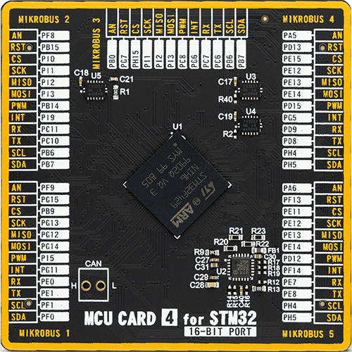
MCU Card / MCU
Type
8th Generation
Architecture
ARM Cortex-M4
MCU Memory (KB)
2048
Silicon Vendor
STMicroelectronics
Pin count
216
RAM (Bytes)
262144
Used MCU Pins
mikroBUS™ mapper
Take a closer look
Click board™ Schematic

Step by step
Project assembly

Start by selecting your development board and Click board™. Begin with the UNI-DS v8 as your development board.


Track your results in real time
Application Output
1. Application Output - In Debug mode, the 'Application Output' window enables real-time data monitoring, offering direct insight into execution results. Ensure proper data display by configuring the environment correctly using the provided tutorial.

2. UART Terminal - Use the UART Terminal to monitor data transmission via a USB to UART converter, allowing direct communication between the Click board™ and your development system. Configure the baud rate and other serial settings according to your project's requirements to ensure proper functionality. For step-by-step setup instructions, refer to the provided tutorial.

3. Plot Output - The Plot feature offers a powerful way to visualize real-time sensor data, enabling trend analysis, debugging, and comparison of multiple data points. To set it up correctly, follow the provided tutorial, which includes a step-by-step example of using the Plot feature to display Click board™ readings. To use the Plot feature in your code, use the function: plot(*insert_graph_name*, variable_name);. This is a general format, and it is up to the user to replace 'insert_graph_name' with the actual graph name and 'variable_name' with the parameter to be displayed.

Software Support
Library Description
This library contains API for Wheatstone Click driver.
Key functions:
wheatstone_set_potentiometer- Set potentiometer ( 0 - 100k )wheatstone_read_an_pin_voltage- This function reads results of AD conversion of the AN pin and converts them to proportional voltage level.
Open Source
Code example
The complete application code and a ready-to-use project are available through the NECTO Studio Package Manager for direct installation in the NECTO Studio. The application code can also be found on the MIKROE GitHub account.
/*!
 * \file
 * \brief Wheatstone Click example
 *
 * # Description
 * This example demonstrates the use of Wheatstone Click board by measuring the input
 * resistance.
 *
 * The demo application is composed of two sections :
 *
 * ## Application Init
 * Initializes the driver and logger and sets the default potentiometer (gain) level.
 *
 * ## Application Task
 * Reads the AN pin voltage and calculates the input resistance from it.
 * All data are being displayed on the USB UART where you can track their changes.
 *
 * @note
 * The following formulas you may find useful:
 * AN_PIN(V) = ( ( 1kOhm + R_INPUT(kOhm) ) / ( 1kOhm + 2*R_INPUT(kOhm) ) - 1/2 ) * VCC(V) * GAIN
 * VOUT(V) = AN_PIN(V) / GAIN
 * R_INPUT(kOhm) = ( VCC(V) * GAIN - 2*AN_PIN(V) ) / ( 4*AN_PIN(V) )
 * R_INPUT(kOhm) = ( VCC(V) - 2*VOUT(V) ) / ( 4*VOUT(V) )
 *
 * \author MikroE Team
 *
 */
// ------------------------------------------------------------------- INCLUDES

#include "board.h"
#include "log.h"
#include "wheatstone.h"

// ------------------------------------------------------------------ VARIABLES

static wheatstone_t wheatstone;
static log_t logger;

// ------------------------------------------------------ APPLICATION FUNCTIONS

void application_init ( void )
{
    log_cfg_t log_cfg;
    wheatstone_cfg_t cfg;

    /**
     * Logger initialization.
     * Default baud rate: 115200
     * Default log level: LOG_LEVEL_DEBUG
     * @note If USB_UART_RX and USB_UART_TX
     * are defined as HAL_PIN_NC, you will
     * need to define them manually for log to work.
     * See @b LOG_MAP_USB_UART macro definition for detailed explanation.
     */
    LOG_MAP_USB_UART( log_cfg );
    log_init( &logger, &log_cfg );
    log_info( &logger, " Application Init " );

    // Click initialization.
    wheatstone_cfg_setup( &cfg );
    WHEATSTONE_MAP_MIKROBUS( cfg, MIKROBUS_1 );
    wheatstone_init( &wheatstone, &cfg );

    wheatstone_set_potentiometer ( &wheatstone, WHEATSTONE_POT_MAX );

    log_info( &logger, " Application Task " );
}

void application_task ( void )
{
    float an_pin_v = 0;
    float vout = 0;
    float r_kohm = 0;
    if ( WHEATSTONE_OK == wheatstone_read_an_pin_voltage ( &wheatstone, &an_pin_v ) )
    {
        vout = an_pin_v / wheatstone.gain;
        if ( 0 != vout )
        {
            r_kohm = ( WHEATSTONE_VCC_5V - 2 * vout ) / ( 4 * vout );
        }
        log_printf( &logger, " VCC     : %.3f V\r\n", WHEATSTONE_VCC_5V );
        log_printf( &logger, " GAIN    : %.3f\r\n", wheatstone.gain );
        log_printf( &logger, " AN_PIN  : %.3f V\r\n", an_pin_v );
        log_printf( &logger, " VOUT    : %.3f V\r\n", vout );
        log_printf( &logger, " R_INPUT : %.3f kOhm\r\n\n", r_kohm );
        Delay_ms ( 1000 );
    }
}

int main ( void )
{
    /* Do not remove this line or clock might not be set correctly. */
    #ifdef PREINIT_SUPPORTED
    preinit();
    #endif

    application_init( );

    for ( ; ; )
    {
        application_task( );
    }

    return 0;
}

// ------------------------------------------------------------------------ END
Additional Support
Resources
Category:Measurements


