Manage fan speeds with MAX6615 and TM4C129ENCPDT for a better tomorrow
Where comfort meets control

Published Jul 26, 2023
Click board™
Fan 8 Click
Dev. board
Fusion for Tiva v8
Compiler
NECTO Studio
MCU
TM4C129ENCPDT
Enhance workplace productivity with our fan speed management solution, maintaining a comfortable and conducive environment for everyone
A
A
Hardware Overview
How does it work?
Fan 8 Click is based on the MAX6615, a compliant fan controller, and accurately two temperature-channels monitors from Analog Devices. The MAX6615 monitors either the internal die temperature or the temperature of external thermistors connected on the onboard headers labeled as TH and reports temperature values in digital form using a 2-wire serial interface. To adjust the speed of the cooling fans, the temperature data controls the duty cycle of a PWM output signal, which minimizes noise when the system is running cool but provides maximum cooling when power dissipation increases. Fan 8 Click communicates with MCU using the standard I2C 2-Wire interface to read data and configure settings with a maximum frequency of 400kHz. Besides, it also allows the choice of the least significant bit of its I2C slave address by
positioning the SMD jumpers labeled ADDR SEL to an appropriate position marked as 0 and 1. This way, the MAX6616 provides the opportunity of the nine possible different I2C addresses by positioning the SMD jumper to an appropriate position. The MAX6615 monitors the fans’ tachometer signals to detect fan failure. When the fan tachometer count is larger than the fan tachometer limit, the fan is considered failing. If that happens, the FAN_FAIL output represented by the FF pin, routed on the PWM pin of the mikroBUS™ socket, is asserted. Also, the MAX6615 features an over-temperature indicator routed on the AN pin of the mikroBUS™ socket, which sets high when a thermal fault occurs and can be used as a warning flag to initiate the system shutdown or to throttle clock frequency. In case of any irregularities, the MCU will also receive information
from an FLT pin (fault indicator), routed on the INT pin of the mikroBUS™ socket, in case further necessary configurations are necessary for proper operation. The Fan 8 Click supports an external fan power supply, connected to the input terminal labeled as VFAN with the value of 5V or 12V, while the fan connection wires can be connected to the onboard headers labeled as FAN1 and FAN2. This Click board™ can operate with both 3.3V and 5V logic voltage levels selected via the VCC SEL jumper. This way, it is allowed for both 3.3V and 5V capable MCUs to use the I2C communication lines properly. However, the Click board™ comes equipped with a library containing easy-to-use functions and an example code that can be used, as a reference, for further development.

Features overview
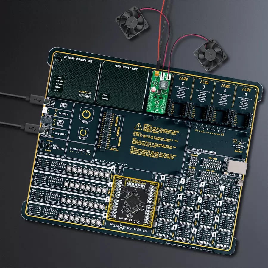
Development board
Fusion for TIVA v8 is a development board specially designed for the needs of rapid development of embedded applications. It supports a wide range of microcontrollers, such as different 32-bit ARM® Cortex®-M based MCUs from Texas Instruments, regardless of their number of pins, and a broad set of unique functions, such as the first-ever embedded debugger/programmer over a WiFi network. The development board is well organized and designed so that the end-user has all the necessary elements, such as switches, buttons, indicators, connectors, and others, in one place. Thanks to innovative manufacturing technology, Fusion for TIVA v8 provides a fluid and immersive working experience, allowing access
anywhere and under any circumstances at any time. Each part of the Fusion for TIVA v8 development board contains the components necessary for the most efficient operation of the same board. An advanced integrated CODEGRIP programmer/debugger module offers many valuable programming/debugging options, including support for JTAG, SWD, and SWO Trace (Single Wire Output)), and seamless integration with the Mikroe software environment. Besides, it also includes a clean and regulated power supply module for the development board. It can use a wide range of external power sources, including a battery, an external 12V power supply, and a power source via the USB Type-C (USB-C) connector.
Communication options such as USB-UART, USB HOST/DEVICE, CAN (on the MCU card, if supported), and Ethernet is also included. In addition, it also has the well-established mikroBUS™ standard, a standardized socket for the MCU card (SiBRAIN standard), and two display options for the TFT board line of products and character-based LCD. Fusion for TIVA v8 is an integral part of the Mikroe ecosystem for rapid development. Natively supported by Mikroe software tools, it covers many aspects of prototyping and development thanks to a considerable number of different Click boards™ (over a thousand boards), the number of which is growing every day.

Microcontroller Overview
MCU Card / MCU

Type
8th Generation
Architecture
ARM Cortex-M4
MCU Memory (KB)
1024
Silicon Vendor
Texas Instruments
Pin count
128
RAM (Bytes)
262144
Used MCU Pins
mikroBUS™ mapper
Take a closer look
Click board™ Schematic

Step by step
Project assembly

Start by selecting your development board and Click board™. Begin with the Fusion for Tiva v8 as your development board.


Software Support
Library Description
This library contains API for Fan 8 Click driver.
Key functions:
fan8_set_duty_cycle- This function sets the duty cycle of the selected fan channel and waits until the duty cycle is set at the PWM outputfan8_measure_rpm- This function measures the RPM of the selected fan channelfan8_read_temperature- This function reads the temperature from the thermistor attached to the selected temperature channel
Open Source
Code example
The complete application code and a ready-to-use project are available through the NECTO Studio Package Manager for direct installation in the NECTO Studio. The application code can also be found on the MIKROE GitHub account.
/*!
 * @file main.c
 * @brief FAN8 Click example
 *
 * # Description
 * This example demonstrates the use of FAN 8 Click board.
 *
 * The demo application is composed of two sections :
 *
 * ## Application Init
 * Initializes the driver and performs the Click default configuration.
 *
 * ## Application Task
 * Changes the speed of fans at both channels by changing the PWM duty cycle, then calculates
 * the fans RPM from measured tachometer signal. It also reads the temperature of two thermistors.
 * The results are being displayed via USB UART where you can track their changes.
 *
 * @note
 * The MAX6615 measures the tachometer signal every 67s, therefore
 * the fan RPM value will be updated once per 67s.
 * An NTC 10K3 thermistor is required for proper temperature measurements.
 *
 * @author Stefan Filipovic
 *
 */

#include "board.h"
#include "log.h"
#include "fan8.h"

static fan8_t fan8;
static log_t logger;

void application_init ( void )
{
    log_cfg_t log_cfg;    /**< Logger config object. */
    fan8_cfg_t fan8_cfg;  /**< Click config object. */

    /**
     * Logger initialization.
     * Default baud rate: 115200
     * Default log level: LOG_LEVEL_DEBUG
     * @note If USB_UART_RX and USB_UART_TX
     * are defined as HAL_PIN_NC, you will
     * need to define them manually for log to work.
     * See @b LOG_MAP_USB_UART macro definition for detailed explanation.
     */
    LOG_MAP_USB_UART( log_cfg );
    log_init( &logger, &log_cfg );
    log_info( &logger, " Application Init " );

    // Click initialization.
    fan8_cfg_setup( &fan8_cfg );
    FAN8_MAP_MIKROBUS( fan8_cfg, MIKROBUS_1 );
    err_t init_flag = fan8_init( &fan8, &fan8_cfg );
    if ( I2C_MASTER_ERROR == init_flag )
    {
        log_error( &logger, " Application Init Error. " );
        log_info( &logger, " Please, run program again... " );

        for ( ; ; );
    }

    init_flag = fan8_default_cfg ( &fan8 );
    if ( FAN8_ERROR == init_flag )
    {
        log_error( &logger, " Default Config Error. " );
        log_info( &logger, " Please, run program again... " );

        for ( ; ; );
    }

    log_info( &logger, " Application Task " );
}

void application_task ( void )
{
    static uint8_t duty_cnt = FAN8_MIN_DUTY_CYCLE;
    static int8_t duty_inc = FAN8_DUTY_CYCLE_STEP_10;
    uint16_t fan_rpm = 0;
    float temperature = 0;

    if ( duty_cnt == FAN8_MAX_DUTY_CYCLE )
    {
        duty_inc = -FAN8_DUTY_CYCLE_STEP_10;
    }
    else if ( duty_cnt == ( FAN8_MIN_DUTY_CYCLE + FAN8_DUTY_CYCLE_STEP_10 ) )
    {
        duty_inc = FAN8_DUTY_CYCLE_STEP_10;
    }
    duty_cnt += duty_inc;

    log_printf( &logger, " - Channel 1 values -\r\n" );
    fan8_set_duty_cycle ( &fan8, FAN8_FAN_CHANNEL_1, duty_cnt );
    log_printf( &logger, " PWM Duty Cycle : %d\r\n", ( uint16_t ) duty_cnt );
    fan8_measure_rpm ( &fan8, FAN8_FAN_CHANNEL_1, FAN8_2_PULSES_PER_REVOLUTION, &fan_rpm );
    log_printf( &logger, " Last measured fan RPM : %u\r\n", fan_rpm );
    fan8_read_temperature ( &fan8, FAN8_TEMP_CHANNEL_1, &temperature );
    log_printf( &logger, " Temperature : %.2f C\r\n\r\n", temperature );

    log_printf( &logger, " - Channel 2 values -\r\n" );
    fan8_set_duty_cycle ( &fan8, FAN8_FAN_CHANNEL_2, duty_cnt );
    log_printf( &logger, " PWM Duty Cycle : %d\r\n", ( uint16_t ) duty_cnt );
    fan8_measure_rpm ( &fan8, FAN8_FAN_CHANNEL_2, FAN8_2_PULSES_PER_REVOLUTION, &fan_rpm );
    log_printf( &logger, " Last measured fan RPM : %u\r\n", fan_rpm );
    fan8_read_temperature ( &fan8, FAN8_TEMP_CHANNEL_2, &temperature );
    log_printf( &logger, " Temperature : %.2f C\r\n\r\n", temperature );

    if ( !fan8_check_fault_indicator ( &fan8 ) )
    {
        log_printf( &logger, " Fault detected!\r\n\r\n", temperature );
    }

    Delay_ms ( 500 );
}

int main ( void )
{
    /* Do not remove this line or clock might not be set correctly. */
    #ifdef PREINIT_SUPPORTED
    preinit();
    #endif

    application_init( );

    for ( ; ; )
    {
        application_task( );
    }

    return 0;
}

// ------------------------------------------------------------------------ END


