Achieve control of bipolar stepper motors and small brushed DC motors with MC34933 and STM32F302VC
Dual H-bridge driver capable of driving loads with a high current of up to 1A

Published Jul 22, 2025
Click board™
H-Bridge Click
Dev. board
CLICKER 4 for STM32F302VCT6
Compiler
NECTO Studio
MCU
STM32F302VC
Control motors in projects requiring precise movement and positioning like 3D printers, precision actuators, and other automated systems
A
A
Hardware Overview
How does it work?
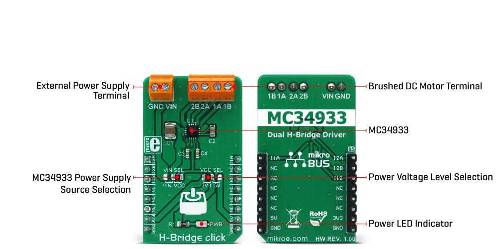
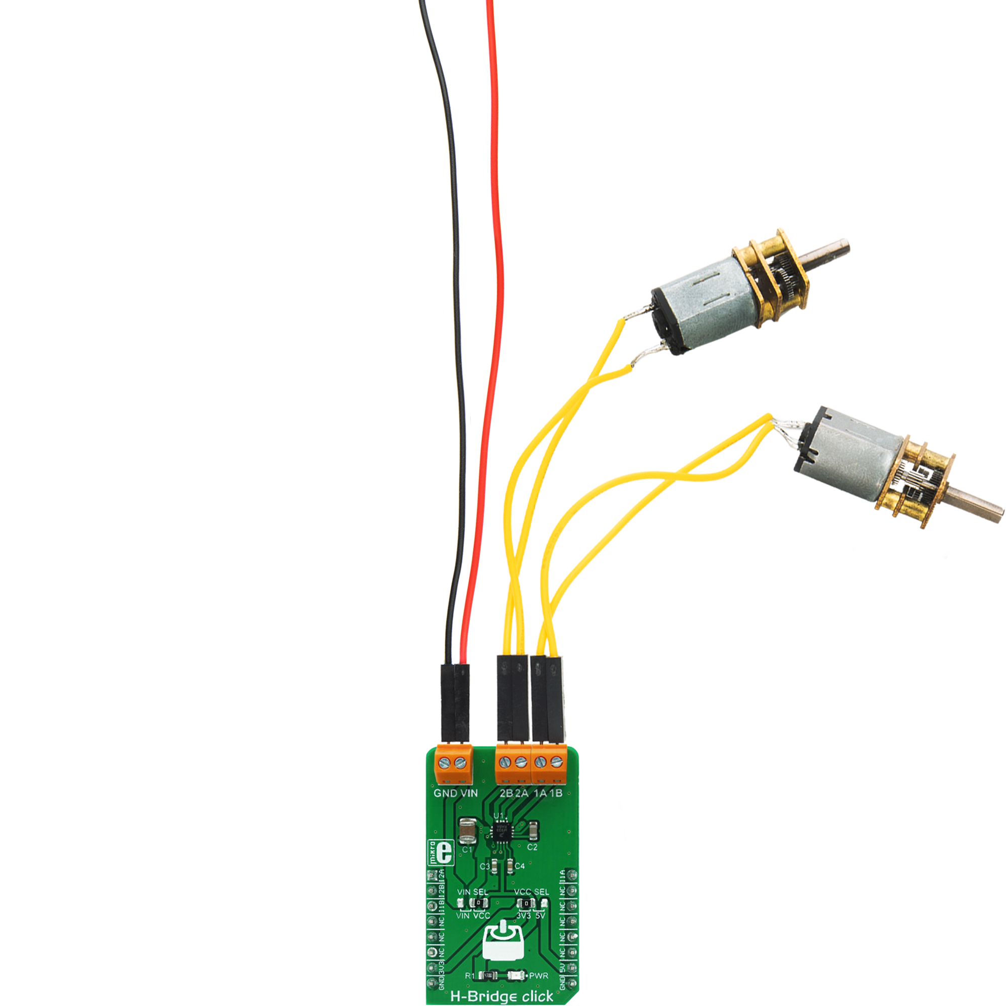
H-Bridge Click is based on the MC34933, a dual H-bridge driver from NXP Semiconductor. This IC is a highly integrated device that requires a minimal number of external elements. Each of the H-bridge channels features two high-side and two low-side MOSFETs, used to control the current flow through the motor's coils. The driver IC is produced using Freescale's proprietary SMARTMOS process, which ensures high efficiency and low power consumption. The total resistance across the output stage drivers is only 0.8Ω, allowing peak currents up to 1.5A and 1A for normal operation at 25˚C. Driving H-bridge channels (and the connected load) is implemented by using four control input lines, two per channel. The truth table below illustrates how the control inputs affect the output stages. H-Bridge click can be used to drive bipolar step motors in full-step or half-step mode, offering full control over the motor driving functions. The H-Bridge click can also be used to drive DC brushed motors. Special cases are when both control inputs of a single H-bridge channel are set to a HIGH or a LOW logic state. In the first case, the output stage will be set to a high impedance (Hi-Z) mode. In the
second case, both outputs of the H-bridge Click will be tied up to the GND, discharging the remaining coil current and performing so-called rheostatic (dynamic) braking. The Hi-Z mode is also activated as a protection measure when the temperature is too high or when the power supply voltage drops under a certain threshold. The control inputs are routed to the mikroBUS™ pins for an easy connection with the MCU. IN1A and IN1B control pins of the MC34933 driver IC used to control the first H-bridge channel are routed to the PWM and CS pins of the mikroBUS™, respectively, while the IN2A and IN2B control pins are routed to the AN and RST pins of the mikroBUS™. These pins are labeled as I1A, I2A, I1B, I2B, on the Click board™. The power supply for the logic section of the IC is provided by the mikroBUS™ power rails. The ability of the driver IC to work with logic levels in the range of 3.3V to 5V simplifies the interfacing to MCUs that work with both voltages: it is enough to move the onboard SMD jumper labeled as VCC SEL and select the desired logic voltage level between 3.3V and 5V. The motor coils are supplied with power from either the external power supply or
by the mikroBUS™ power rail, selected with the VCC SEL jumper. When working with motors that consume more power than available at the mikroBUS™ power rail, it is advisable to connect the external power supply and move the jumper labeled as VIN SEL to the VIN position. By default, this jumper is set to use the mikroBUS™ power supply (VCC position). The external DC power supply can be connected to the two-pole input screw terminal, with its inputs labeled as GND and VIN. The stepper motor coils can be connected to the four-pole screw terminal, with its inputs labeled as 1A, 1B, 2A, 2B. These labels correspond to the H-bridge outputs from the driver IC itself: 1A is routed to the OUT1A, 1B to the OUT1B, and more. The Click board™ can be easily driven via the GPIO pins of the host MCU. This Click board™ can operate with either 3.3V or 5V logic voltage levels selected via the VCC SEL jumper. This way, both 3.3V and 5V capable MCUs can use the communication lines properly. Also, this Click board™ comes equipped with a library containing easy-to-use functions and an example code that can be used for further development.
Features overview
Development board
Clicker 4 for STM32F3 is a compact development board designed as a complete solution, you can use it to quickly build your own gadgets with unique functionalities. Featuring a STM32F302VCT6, four mikroBUS™ sockets for Click boards™ connectivity, power managment, and more, it represents a perfect solution for the rapid development of many different types of applications. At its core, there is a STM32F302VCT6 MCU, a powerful microcontroller by STMicroelectronics, based on the high-
performance Arm® Cortex®-M4 32-bit processor core operating at up to 168 MHz frequency. It provides sufficient processing power for the most demanding tasks, allowing Clicker 4 to adapt to any specific application requirements. Besides two 1x20 pin headers, four improved mikroBUS™ sockets represent the most distinctive connectivity feature, allowing access to a huge base of Click boards™, growing on a daily basis. Each section of Clicker 4 is clearly marked, offering an intuitive and clean interface. This makes working with the development
board much simpler and thus, faster. The usability of Clicker 4 doesn’t end with its ability to accelerate the prototyping and application development stages: it is designed as a complete solution which can be implemented directly into any project, with no additional hardware modifications required. Four mounting holes [4.2mm/0.165”] at all four corners allow simple installation by using mounting screws. For most applications, a nice stylish casing is all that is needed to turn the Clicker 4 development board into a fully functional, custom design.

Microcontroller Overview
MCU Card / MCU

Architecture
ARM Cortex-M4
MCU Memory (KB)
256
Silicon Vendor
STMicroelectronics
Pin count
100
RAM (Bytes)
40960
You complete me!
Accessories
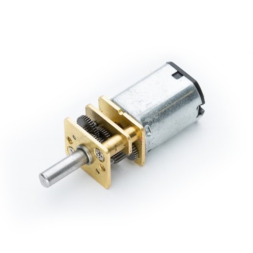
DC Gear Motor - 430RPM (3-6V) represents an all-in-one combination of a motor and gearbox, where the addition of gear leads to a reduction of motor speed while increasing the torque output. This gear motor has a spur gearbox, making it a highly reliable solution for applications with lower torque and speed requirements. The most critical parameters for gear motors are speed, torque, and efficiency, which are, in this case, 520RPM with no load and 430RPM at maximum efficiency, alongside a current of 60mA and a torque of 50g.cm. Rated for a 3-6V operational voltage range and clockwise/counterclockwise rotation direction, this motor represents an excellent solution for many functions initially performed by brushed DC motors in robotics, medical equipment, electric door locks, and much more.
Used MCU Pins
mikroBUS™ mapper
Take a closer look
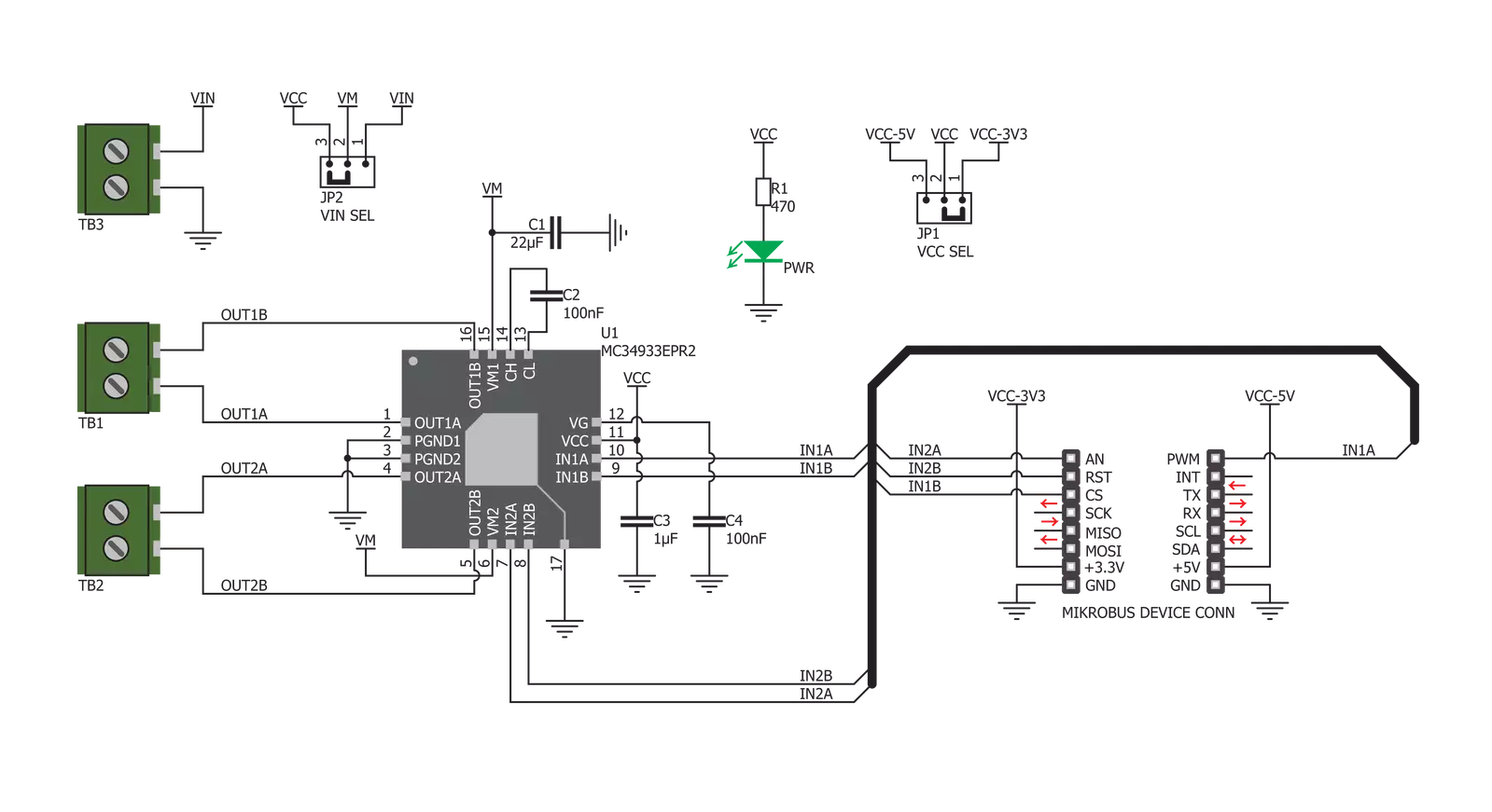
Click board™ Schematic
Step by step
Project assembly

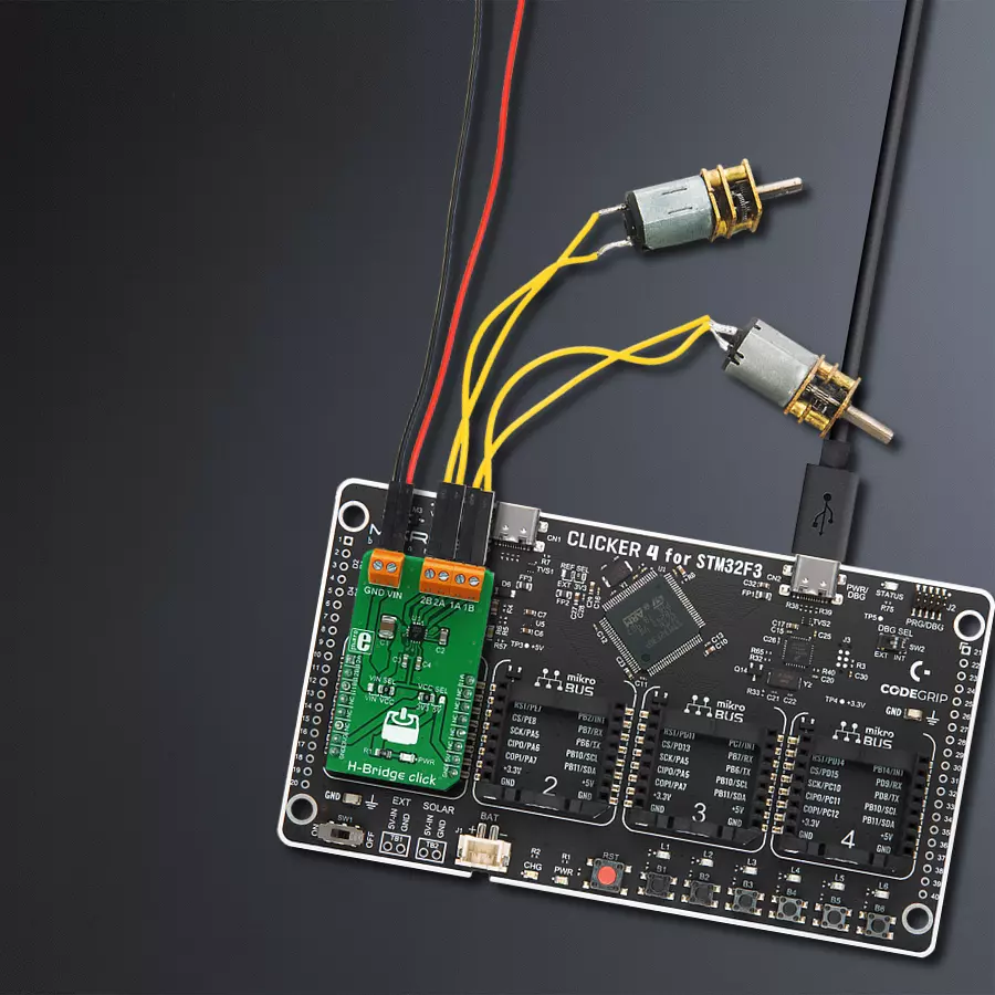
Start by selecting your development board and Click board™. Begin with the CLICKER 4 for STM32F302VCT6 as your development board.


Track your results in real time
Application Output
1. Application Output - In Debug mode, the 'Application Output' window enables real-time data monitoring, offering direct insight into execution results. Ensure proper data display by configuring the environment correctly using the provided tutorial.

2. UART Terminal - Use the UART Terminal to monitor data transmission via a USB to UART converter, allowing direct communication between the Click board™ and your development system. Configure the baud rate and other serial settings according to your project's requirements to ensure proper functionality. For step-by-step setup instructions, refer to the provided tutorial.

3. Plot Output - The Plot feature offers a powerful way to visualize real-time sensor data, enabling trend analysis, debugging, and comparison of multiple data points. To set it up correctly, follow the provided tutorial, which includes a step-by-step example of using the Plot feature to display Click board™ readings. To use the Plot feature in your code, use the function: plot(*insert_graph_name*, variable_name);. This is a general format, and it is up to the user to replace 'insert_graph_name' with the actual graph name and 'variable_name' with the parameter to be displayed.

Software Support
Library Description
This library contains API for H-Bridge Click driver.
Key functions:
hbridge_set_step_mode- This function sets the step mode resolution settings in @b ctx->step_modehbridge_set_direction- This function sets the motor direction to clockwise or counter-clockwise in @b ctx->directionhbridge_drive_motor- This function drives the motor for the specific number of steps at the selected speed
Open Source
Code example
The complete application code and a ready-to-use project are available through the NECTO Studio Package Manager for direct installation in the NECTO Studio. The application code can also be found on the MIKROE GitHub account.
/*!
 * @file main.c
 * @brief H-Bridge Click Example.
 *
 * # Description
 * This example demonstrates the use of the H-Bridge Click board by driving the
 * motor in both directions for a desired number of steps.
 *
 * The demo application is composed of two sections :
 *
 * ## Application Init
 * Initializes the driver and logger.
 *
 * ## Application Task
 * Drives the motor clockwise for 200 full steps and then counter-clockiwse for 400 half
 * steps with a 2 seconds delay before changing the direction. All data is being logged on
 * the USB UART where you can track the program flow.
 *
 * @author Stefan Filipovic
 *
 */

#include "board.h"
#include "log.h"
#include "hbridge.h"

static hbridge_t hbridge;   /**< H-Bridge Click driver object. */
static log_t logger;    /**< Logger object. */

void application_init ( void )
{
    log_cfg_t log_cfg;  /**< Logger config object. */
    hbridge_cfg_t hbridge_cfg;  /**< Click config object. */

    /**
     * Logger initialization.
     * Default baud rate: 115200
     * Default log level: LOG_LEVEL_DEBUG
     * @note If USB_UART_RX and USB_UART_TX
     * are defined as HAL_PIN_NC, you will
     * need to define them manually for log to work.
     * See @b LOG_MAP_USB_UART macro definition for detailed explanation.
     */
    LOG_MAP_USB_UART( log_cfg );
    log_init( &logger, &log_cfg );
    log_info( &logger, " Application Init " );

    // Click initialization.
    hbridge_cfg_setup( &hbridge_cfg );
    HBRIDGE_MAP_MIKROBUS( hbridge_cfg, MIKROBUS_1 );
    if ( DIGITAL_OUT_UNSUPPORTED_PIN == hbridge_init( &hbridge, &hbridge_cfg ) )
    {
        log_error( &logger, " Communication init." );
        for ( ; ; );
    }

    log_info( &logger, " Application Task " );
}

void application_task ( void )
{
    hbridge_set_step_mode ( &hbridge, HBRIDGE_MODE_FULL_STEP );
    hbridge_set_direction ( &hbridge, HBRIDGE_DIR_CW );
    hbridge_drive_motor ( &hbridge, 200, HBRIDGE_SPEED_MEDIUM );
    log_printf ( &logger, " Move 200 full steps clockwise\r\n\n" );
    Delay_ms ( 1000 );
    Delay_ms ( 1000 );

    hbridge_set_step_mode ( &hbridge, HBRIDGE_MODE_HALF_STEP );
    hbridge_set_direction ( &hbridge, HBRIDGE_DIR_CCW );
    hbridge_drive_motor ( &hbridge, 400, HBRIDGE_SPEED_FAST );
    log_printf ( &logger, " Move 400 half steps counter-clockwise\r\n\n" );
    Delay_ms ( 1000 );
    Delay_ms ( 1000 );
}

int main ( void )
{
    /* Do not remove this line or clock might not be set correctly. */
    #ifdef PREINIT_SUPPORTED
    preinit();
    #endif

    application_init( );

    for ( ; ; )
    {
        application_task( );
    }

    return 0;
}

// ------------------------------------------------------------------------ END
Additional Support
Resources
Category:Brushed


