Gain superior control and orientation capabilities with MC6470 and PIC24HJ256GP610
Versatile control in a compact package: The ultimate IMU

Published Sep 27, 2023
Click board™
6DOF IMU 13 Click
Dev. board
Fusion for PIC v8
Compiler
NECTO Studio
MCU
PIC24HJ256GP610
Achieve exceptional precision in directional sensing, allowing for more accurate tracking and positioning in your projects
A
A
Hardware Overview
How does it work?
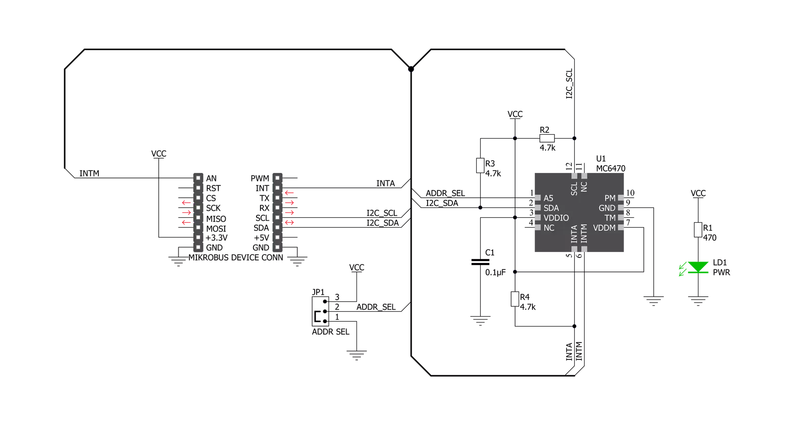
6DOF IMU 13 Click is based on the MC6470 that combines an accelerometer and magnetometer for a 6 DoF (6 Degrees of Freedom) sensor solution from mCube. An accelerometer has two states of operation: STANDBY, which is its default state after the Power-Up function, and WAKE. The STANDBY state offers the lowest power consumption, and only in this state the I2C interface is active, and all register reads and writes are allowed. This state has no event detection, sampling, or acceleration measurement. Only write access is permitted to the MODE register in the WAKE state. The full-scale acceleration range can be adjusted from ±2g up to ±16g with a 14-bit resolution. This Click board™ also includes a high-performance magnetic sensor with 0.15μT resolution, a broad field range up to ±2.4mT, and a programmable output data rate from 0.5 to 100 Hz. The magnetometer has two operational modes,
Standby and Active Mode with Force and Normal State, whose primary purpose is power management. It also provides additional functions such as the Data Ready Function, which occurs when new measured results are updated, Offset Calibration and Drift Functions, and the Temperature Measurement Function, which retrieves temperature data for internal compensation of output data from an internal temperature sensor. Each axis's magnetic sensor output value is positive when turned toward the magnetic north. The MC6470 possesses two interrupt outputs, a magnetometer (IN2) and an accelerometer (IN1) interrupts, routed to the AN and INT pins on the mikroBUS™ used to signal MCU that an event has been sensed. It also supports directional tap detection in ±X, ±Y, or ±Z axis, where each axis is independent, although only one direction per axis is supported
simultaneously. In this case, the interrupt pins can indicate that a tap event has been detected. 6DOF IMU 13 Click communicates with MCU using the standard I2C 2-Wire interface with a maximum frequency of 400kHz. The MC6470 always operates as an I2C peripheral device on both magnetometer and accelerometer I2C interfaces. It allows the choice of the least significant bit (LSB) of its I2C slave address, which can be done using the SMD jumper labeled ADDR SEL. This Click board™ can be operated only with a 3.3V logic voltage level. The board must perform appropriate logic voltage level conversion before using MCUs with different logic levels. Also, it comes equipped with a library containing functions and an example code that can be used as a reference for further development.


Features overview
Development board
Fusion for PIC v8 is a development board specially designed for the needs of rapid development of embedded applications. It supports a wide range of microcontrollers, such as different PIC, dsPIC, PIC24, and PIC32 MCUs regardless of their number of pins, and a broad set of unique functions, such as the first-ever embedded debugger/programmer over WiFi. The development board is well organized and designed so that the end-user has all the necessary elements, such as switches, buttons, indicators, connectors, and others, in one place. Thanks to innovative manufacturing technology, Fusion for PIC v8 provides a fluid and immersive working experience, allowing access anywhere and under any
circumstances at any time. Each part of the Fusion for PIC v8 development board contains the components necessary for the most efficient operation of the same board. In addition to the advanced integrated CODEGRIP programmer/debugger module, which offers many valuable programming/debugging options and seamless integration with the Mikroe software environment, the board also includes a clean and regulated power supply module for the development board. It can use a wide range of external power sources, including a battery, an external 12V power supply, and a power source via the USB Type-C (USB-C) connector. Communication options such as USB-UART, USB
HOST/DEVICE, CAN (on the MCU card, if supported), and Ethernet are also included, including the well-established mikroBUS™ standard, a standardized socket for the MCU card (SiBRAIN standard), and two display options (graphical and character-based LCD). Fusion for PIC v8 is an integral part of the Mikroe ecosystem for rapid development. Natively supported by Mikroe software tools, it covers many aspects of prototyping and development thanks to a considerable number of different Click boards™ (over a thousand boards), the number of which is growing every day.

Microcontroller Overview
MCU Card / MCU
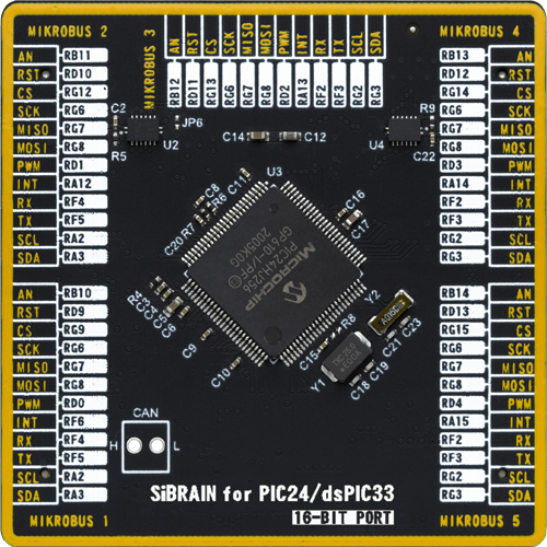
Type
8th Generation
Architecture
dsPIC
MCU Memory (KB)
256
Silicon Vendor
Microchip
Pin count
100
RAM (Bytes)
16384
Used MCU Pins
mikroBUS™ mapper
Take a closer look
Click board™ Schematic
Step by step
Project assembly

Start by selecting your development board and Click board™. Begin with the Fusion for PIC v8 as your development board.


Track your results in real time
Application Output
1. Application Output - In Debug mode, the 'Application Output' window enables real-time data monitoring, offering direct insight into execution results. Ensure proper data display by configuring the environment correctly using the provided tutorial.

2. UART Terminal - Use the UART Terminal to monitor data transmission via a USB to UART converter, allowing direct communication between the Click board™ and your development system. Configure the baud rate and other serial settings according to your project's requirements to ensure proper functionality. For step-by-step setup instructions, refer to the provided tutorial.

3. Plot Output - The Plot feature offers a powerful way to visualize real-time sensor data, enabling trend analysis, debugging, and comparison of multiple data points. To set it up correctly, follow the provided tutorial, which includes a step-by-step example of using the Plot feature to display Click board™ readings. To use the Plot feature in your code, use the function: plot(*insert_graph_name*, variable_name);. This is a general format, and it is up to the user to replace 'insert_graph_name' with the actual graph name and 'variable_name' with the parameter to be displayed.

Software Support
Library Description
This library contains API for 6DOF IMU 13 Click driver.
Key functions:
c6dofimu13_mag_get_data- This function reads magnetometer X, Y, and Z-Axis datac6dofimu13_accel_init- This function initializes accelerometerc6dofimu13_accel_get_data- This function reads accelerometer X, Y, and Z-Axis data.
Open Source
Code example
The complete application code and a ready-to-use project are available through the NECTO Studio Package Manager for direct installation in the NECTO Studio. The application code can also be found on the MIKROE GitHub account.
/*!
 * @file main.c
 * @brief 6DOFIMU13 Click example
 *
 * # Description
 * This example demonstrates the use of 6DOF IMU 13 Click board.
 *
 * The demo application is composed of two sections :
 *
 * ## Application Init
 * Initializes the driver, and sets the device default configuration.
 *
 * ## Application Task
 * Measures acceleration and magnetometer data and displays the results on the USB UART every second.
 *
 * @author Stefan Filipovic
 *
 */

#include "board.h"
#include "log.h"
#include "c6dofimu13.h"

static c6dofimu13_t c6dofimu13;
static log_t logger;

void application_init ( void )
{
    log_cfg_t log_cfg;  /**< Logger config object. */
    c6dofimu13_cfg_t c6dofimu13_cfg;  /**< Click config object. */

    /**
     * Logger initialization.
     * Default baud rate: 115200
     * Default log level: LOG_LEVEL_DEBUG
     * @note If USB_UART_RX and USB_UART_TX
     * are defined as HAL_PIN_NC, you will
     * need to define them manually for log to work.
     * See @b LOG_MAP_USB_UART macro definition for detailed explanation.
     */
    LOG_MAP_USB_UART( log_cfg );
    log_init( &logger, &log_cfg );
    Delay_ms ( 100 );

    log_info( &logger, " Application Init " );

    // Click initialization.

    c6dofimu13_cfg_setup( &c6dofimu13_cfg );
    C6DOFIMU13_MAP_MIKROBUS( c6dofimu13_cfg, MIKROBUS_1 );
    err_t init_flag = c6dofimu13_init( &c6dofimu13, &c6dofimu13_cfg );
    if ( init_flag == I2C_MASTER_ERROR )
    {
        log_error( &logger, " Application Init Error. " );
        log_info( &logger, " Please, run program again... " );

        for ( ; ; );
    }

    c6dofimu13_default_cfg ( &c6dofimu13 );
    log_info( &logger, " Application Task " );
}

void application_task ( void )
{
    float acc_x, acc_y, acc_z;
    float mag_x, mag_y, mag_z;

    c6dofimu13_accel_get_data( &c6dofimu13, &acc_x, &acc_y, &acc_z );
    c6dofimu13_mag_get_data( &c6dofimu13, &mag_x, &mag_y, &mag_z );

    log_printf( &logger, " Accel X: %.3f g\t Mag X: %.2f uT\r\n", acc_x, mag_x );
    log_printf( &logger, " Accel Y: %.3f g\t Mag Y: %.2f uT\r\n", acc_y, mag_y );
    log_printf( &logger, " Accel Z: %.3f g\t Mag Z: %.2f uT\r\n", acc_z, mag_z );
    log_printf( &logger, "----------------------------------\r\n");

    Delay_ms ( 1000 );
}

int main ( void )
{
    /* Do not remove this line or clock might not be set correctly. */
    #ifdef PREINIT_SUPPORTED
    preinit();
    #endif

    application_init( );

    for ( ; ; )
    {
        application_task( );
    }

    return 0;
}

// ------------------------------------------------------------------------ END


