Simplify complex CAN network management with ATA6563 and STM32F302VC
High-speed, high-precision: Your CAN network's best companion

Published Jul 22, 2025
Click board™
MCP2518FD Click
Dev. board
CLICKER 4 for STM32F302VCT6
Compiler
NECTO Studio
MCU
STM32F302VC
Elevate your CAN network's capabilities with our high-speed, high-precision transceiver, setting new standards for data transfer within your system.
A
A
Hardware Overview
How does it work?
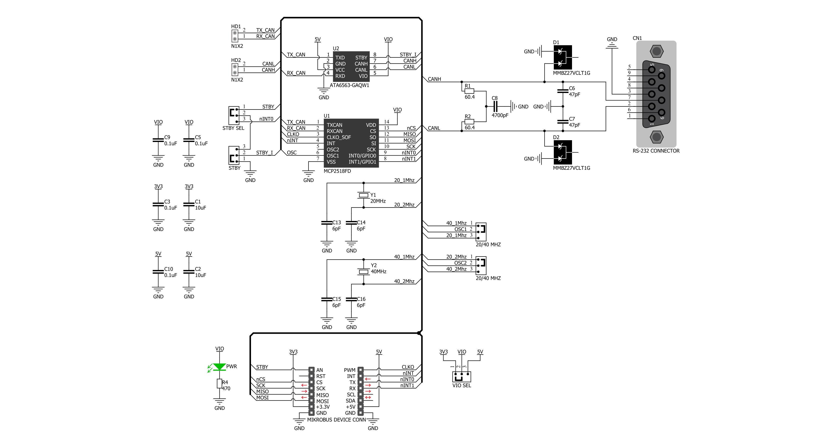
MCP2518FD Click is based on the MCP2518FD and ATA6563, an external CAN FD controller with an SPI interface and a high-speed CAN transceiver from Microchip. The ATA6563, a low-level physical layer IC (PHY), provides a physical connection with the CAN bus, while the CAN controller MCP2518FD represents an interface between the MCU and the PHY. The role of the CAN controller is to provide arbitration, message framing, message validation, error detection, message filtering, and more. Among all other tasks, it offers formatted CAN data for the application layer running on the host MCU. On the other side, the ATA6563, a high-speed CAN transceiver, provides a physical connection with the CAN bus. It allows communication speeds up to 5Mbps and offers high resistance to electrostatic discharge and other electromagnetic phenomena. The ATA6563 supports Normal and Standby operational modes. Normal mode is engaged when the STBY pin, routed on the AN pin of the mikroBUS™ socket, is at the logic low level, while the TXD pin is held to a high logic level. While in the Normal
mode, the data can be transmitted and received via the CAN H/L bus lines. The mode selection can be made by positioning the SMD jumper labeled as STBY to an appropriate position marked as STBY or ON. In the case of Standby mode, if the STBY jumper is set to the STBY position, the user has the option of activating the Standby mode in two ways, where the selection is made by positioning the SMD jumper labeled as STBY SEL to an appropriate position marked as STBY or INT0. In this way, the Standby mode can be activated via the STBY pin from the mikroBUS™ socket or by the MCP2518FD interrupt signal IN0 (the IN0 pin can also be used to alert the MCU about the TX events). The MCP2518FD communicates with the MCU using the SPI interface. In addition, the user can connect the external TX/RX signals to the CAN FD transceiver and CAN bus signals directly through the onboard headers on the right and left sides of the board. This Click board™ comes equipped with the standard DB-9 connector, making interfacing with the CAN bus simple and easy. In addition, this Click
board™ also uses several pins of the mikroBUS™ socket. The CLKO pin from the MCP2518FD routed to the PWM pin of the mikroBUS™ socket can provide the clock output for the host MCU. It is derived from the input clock generated by the onboard chip oscillators, where the onboard SMD jumpers allow frequency selection between 20MHz and 40MHz. Besides, it also uses two interrupt pins, INT and INT1, routed to the INT and RX pins of the mikroBUS™ socket, respectively. While the INT pin is always an interrupt pin used to alert the MCU of the enabled interrupt event, the INT1 pin alerts the MCU about the RX events (if these interrupts are enabled). This Click board™ can operate with either 3.3V or 5V logic voltage levels selected via the VIO SEL jumper. This way, both 3.3V and 5V capable MCUs can use the communication lines properly. Also, this Click board™ comes equipped with a library containing easy-to-use functions and an example code that can be used as a reference for further development.

Features overview
Development board
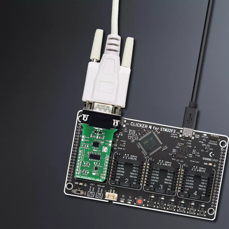
Clicker 4 for STM32F3 is a compact development board designed as a complete solution, you can use it to quickly build your own gadgets with unique functionalities. Featuring a STM32F302VCT6, four mikroBUS™ sockets for Click boards™ connectivity, power managment, and more, it represents a perfect solution for the rapid development of many different types of applications. At its core, there is a STM32F302VCT6 MCU, a powerful microcontroller by STMicroelectronics, based on the high-
performance Arm® Cortex®-M4 32-bit processor core operating at up to 168 MHz frequency. It provides sufficient processing power for the most demanding tasks, allowing Clicker 4 to adapt to any specific application requirements. Besides two 1x20 pin headers, four improved mikroBUS™ sockets represent the most distinctive connectivity feature, allowing access to a huge base of Click boards™, growing on a daily basis. Each section of Clicker 4 is clearly marked, offering an intuitive and clean interface. This makes working with the development
board much simpler and thus, faster. The usability of Clicker 4 doesn’t end with its ability to accelerate the prototyping and application development stages: it is designed as a complete solution which can be implemented directly into any project, with no additional hardware modifications required. Four mounting holes [4.2mm/0.165”] at all four corners allow simple installation by using mounting screws. For most applications, a nice stylish casing is all that is needed to turn the Clicker 4 development board into a fully functional, custom design.

Microcontroller Overview
MCU Card / MCU

Architecture
ARM Cortex-M4
MCU Memory (KB)
256
Silicon Vendor
STMicroelectronics
Pin count
100
RAM (Bytes)
40960
You complete me!
Accessories
DB9 Cable Female-to-Female (2m) cable is essential for establishing dependable serial data connections between devices. With its DB9 female connectors on both ends, this cable enables a seamless link between various equipment, such as computers, routers, switches, and other serial devices. Measuring 2 meters in length, it offers flexibility in arranging your setup without compromising data transmission quality. Crafted with precision, this cable ensures consistent and reliable data exchange, making it suitable for industrial applications, office environments, and home setups. Whether configuring networking equipment, accessing console ports, or utilizing serial peripherals, this cable's durable construction and robust connectors guarantee a stable connection. Simplify your data communication needs with the 2m DB9 female-to-female cable, an efficient solution designed to meet your serial connectivity requirements easily and efficiently.

Used MCU Pins
mikroBUS™ mapper
Take a closer look
Click board™ Schematic
Step by step
Project assembly

Start by selecting your development board and Click board™. Begin with the CLICKER 4 for STM32F302VCT6 as your development board.


Software Support
Library Description
This library contains API for MCP2518FD Click driver.
Key functions:
mcp2518fd_transmit_message- Transmits the desired message and checks is message successfully sent.mcp2518fd_receive_message- Receives the message and checks is message successfully received.mcp2518fd_reset- Function for reset using generic transfer
Open Source
Code example
The complete application code and a ready-to-use project are available through the NECTO Studio Package Manager for direct installation in the NECTO Studio. The application code can also be found on the MIKROE GitHub account.
/*!
 * @file main.c
 * @brief MCP2518FD Click example
 *
 * # Description
 * This example demonstrates the use of an MCP2518FD Click board by showing
 * the communication between the two Click boards configured as a receiver and transmitter.
 *
 * The demo application is composed of two sections :
 *
 * ## Application Init
 * Initializes the driver and logger, performs the Click default configuration and
 * displays the selected application mode.
 *
 * ## Application Task
 * Depending on the selected mode, it sends a desired message using CAN protocol or
 * reads all the received data and displays them on the USB UART.
 *
 * @author Mikroe Team
 *
 */

#include "board.h"
#include "log.h"
#include "mcp2518fd.h"

// Comment out the line below in order to switch the application mode to receiver
#define DEMO_APP_TRANSMITTER

// Text message to send in the transmitter application mode
#define DEMO_TEXT_MESSAGE           "MIKROE\0"

static mcp2518fd_t mcp2518fd;
static log_t logger;

void application_init ( void )
{
    log_cfg_t log_cfg;  /**< Logger config object. */
    mcp2518fd_cfg_t mcp2518fd_cfg;  /**< Click config object. */

    /**
     * Logger initialization.
     * Default baud rate: 115200
     * Default log level: LOG_LEVEL_DEBUG
     * @note If USB_UART_RX and USB_UART_TX
     * are defined as HAL_PIN_NC, you will
     * need to define them manually for log to work.
     * See @b LOG_MAP_USB_UART macro definition for detailed explanation.
     */
    LOG_MAP_USB_UART( log_cfg );
    log_init( &logger, &log_cfg );
    log_info( &logger, " Application Init " );

    // Click initialization.
    mcp2518fd_cfg_setup( &mcp2518fd_cfg );
    MCP2518FD_MAP_MIKROBUS( mcp2518fd_cfg, MIKROBUS_1 );
    if ( SPI_MASTER_ERROR == mcp2518fd_init( &mcp2518fd, &mcp2518fd_cfg ) )
    {
        log_error( &logger, " Communication init." );
        for ( ; ; );
    }

    if ( MCP2518FD_ERROR == mcp2518fd_default_cfg ( &mcp2518fd ) )
    {
        log_error( &logger, " Default configuration." );
        for ( ; ; );
    }

#ifdef DEMO_APP_TRANSMITTER
    log_printf( &logger, " Application Mode: Transmitter\r\n" );
#else
    log_printf( &logger, " Application Mode: Receiver\r\n" );
#endif
    log_info( &logger, " Application Task " );
}

void application_task ( void )
{
#ifdef DEMO_APP_TRANSMITTER
    if ( MCP2518FD_OK == mcp2518fd_transmit_message( &mcp2518fd, DEMO_TEXT_MESSAGE, strlen( DEMO_TEXT_MESSAGE ) ) )
    {
        log_printf( &logger, " The message \"%s\" has been sent!\r\n", ( char * ) DEMO_TEXT_MESSAGE );
    }
    Delay_ms ( 1000 );
    Delay_ms ( 1000 );
#else
    uint8_t data_buf[ 256 ] = { 0 };
    uint16_t data_len = 0;
    if ( MCP2518FD_OK == mcp2518fd_receive_message( &mcp2518fd, data_buf, &data_len ) )
    {
        log_printf( &logger, " A new message has received: \"" );
        for ( uint16_t cnt = 0; cnt < data_len; cnt++ )
        {
            log_printf( &logger, "%c", data_buf[ cnt ] );
        }
        log_printf( &logger, "\"\r\n" );
    }
#endif
}

int main ( void )
{
    /* Do not remove this line or clock might not be set correctly. */
    #ifdef PREINIT_SUPPORTED
    preinit();
    #endif

    application_init( );

    for ( ; ; )
    {
        application_task( );
    }

    return 0;
}

// ------------------------------------------------------------------------ END
Additional Support
Resources
Category:CAN


