Establish wireless communication and achieve remote data collection with Metis-I (2605041183000) and STM32L496AG
Low-power 868MHz radio module for utility metering and telemetry
Published Jul 22, 2025
Click board™
M-BUS RF 2 Click
Dev. board
Discovery kit with STM32L496AG MCU
Compiler
NECTO Studio
MCU
STM32L496AG
Transmit and receive data wirelessly up to 700 meters for utility metering and telemetry using the Wireless M-BUS and Open Metering System (OMS) standards.
A
A
Hardware Overview
How does it work?
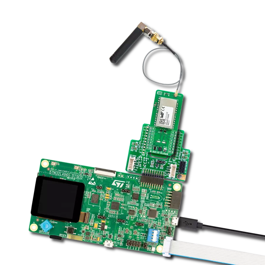
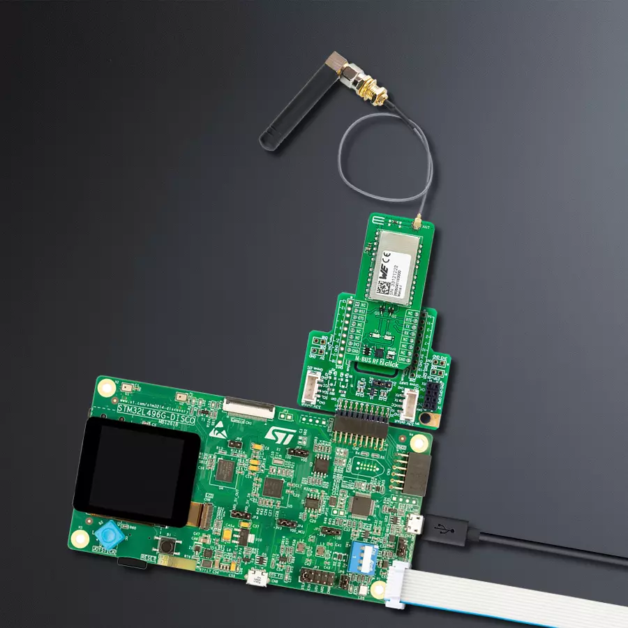
M-BUS RF 2 Click is based on the Metis-I (2605041183000), a radio module from Würth Elektronik, operating at 868MHz frequency. This module integrates an MSP430 microcontroller and a CC1101 RF chip-set, providing a powerful yet low-cost communication solution. The Metis-I module has a range of impressive features. Operating on a frequency band of 868MHz, it is also equipped with a 32768B Flash memory and 1024B RAM. It adheres to the Wireless M-BUS EN13757-4:2013 standard and supports the Open Metering System (OMS), ensuring broad compatibility in utility metering applications. The module can communicate effectively over distances
up to 700 meters under clear conditions and is designed with energy efficiency in mind, including a Wake-On-Radio feature that reduces power consumption. Additionally, it has an output power of +11dBm and an RF sensitivity of up to -103dBm for robust wireless transmission. Communication between the Metis-I and the host MCU is made through a UART interface, using the standard UART RX and TX pins and hardware flow control pins (CTS/RTS). The module communicates at 115200bps by default, allowing efficient data exchange. The board also includes a reset (RST) pin for resetting the module. There are two LED indicators for user interaction: an orange TX LED
signaling transmission activity and a yellow RX LED indicating reception. The board is designed to interface with 868MHz antennas, such as the Rubber 868MHz Antenna offered by MIKROE. It includes a u.Fl connector, necessitating an IPEX-SMA cable adapter, also available from MIKROE, to ensure proper antenna connection. This Click board™ can be operated only with a 3.3V logic voltage level. The board must perform appropriate logic voltage level conversion before using MCUs with different logic levels. Also, it comes equipped with a library containing functions and an example code that can be used as a reference for further development.

Features overview
Development board
The 32L496GDISCOVERY Discovery kit serves as a comprehensive demonstration and development platform for the STM32L496AG microcontroller, featuring an Arm® Cortex®-M4 core. Designed for applications that demand a balance of high performance, advanced graphics, and ultra-low power consumption, this kit enables seamless prototyping for a wide range of embedded solutions. With its innovative energy-efficient
architecture, the STM32L496AG integrates extended RAM and the Chrom-ART Accelerator, enhancing graphics performance while maintaining low power consumption. This makes the kit particularly well-suited for applications involving audio processing, graphical user interfaces, and real-time data acquisition, where energy efficiency is a key requirement. For ease of development, the board includes an onboard ST-LINK/V2-1
debugger/programmer, providing a seamless out-of-the-box experience for loading, debugging, and testing applications without requiring additional hardware. The combination of low power features, enhanced memory capabilities, and built-in debugging tools makes the 32L496GDISCOVERY kit an ideal choice for prototyping advanced embedded systems with state-of-the-art energy efficiency.

Microcontroller Overview
MCU Card / MCU

Architecture
ARM Cortex-M4
MCU Memory (KB)
1024
Silicon Vendor
STMicroelectronics
Pin count
169
RAM (Bytes)
327680
You complete me!
Accessories
868MHz right-angle rubber antenna is a compact and versatile solution for wireless communication. Operating within the frequency range of 868-915MHz, it ensures optimal signal reception and transmission. With a 50-ohm impedance, it's compatible with various devices and systems. This antenna boasts a 2dB gain, enhancing signal strength and extending communication range. Its vertical polarization further contributes to signal clarity. Designed to handle up to 50W of input power, it's a robust choice for various applications. Measuring just 48mm in length, this antenna is both discreet and practical. Its SMA male connector ensures a secure and reliable connection to your equipment. Whether you're working with IoT devices, remote sensors, or other wireless technologies, the 868MHz right-angle antenna offers the performance and flexibility you need for seamless communication.

IPEX-SMA cable is a type of RF (radio frequency) cable assembly. "IPEX" refers to the IPEX connector, a miniature coaxial connector commonly used in small electronic devices. "SMA" stands for SubMiniature Version A and is another coaxial connector commonly used in RF applications. An IPEX-SMA cable assembly has an IPEX connector on one end and an SMA connector on the other, allowing it to connect devices or components that use these specific connectors. These cables are often used in applications like WiFi or cellular antennas, GPS modules, and other RF communication systems where a reliable and low-loss connection is required.

Used MCU Pins
mikroBUS™ mapper
Take a closer look
Click board™ Schematic

Step by step
Project assembly

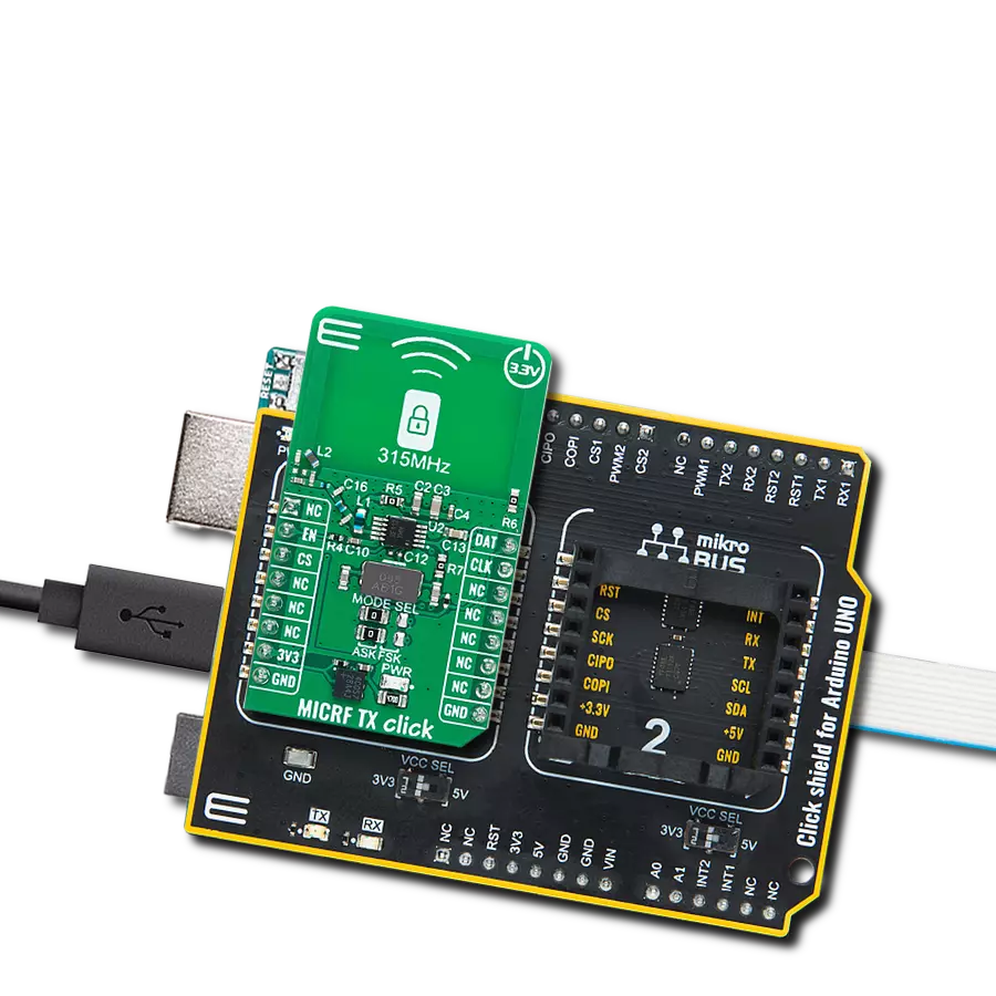
Start by selecting your development board and Click board™. Begin with the Discovery kit with STM32L496AG MCU as your development board.


Track your results in real time
Application Output
1. Application Output - In Debug mode, the 'Application Output' window enables real-time data monitoring, offering direct insight into execution results. Ensure proper data display by configuring the environment correctly using the provided tutorial.

2. UART Terminal - Use the UART Terminal to monitor data transmission via a USB to UART converter, allowing direct communication between the Click board™ and your development system. Configure the baud rate and other serial settings according to your project's requirements to ensure proper functionality. For step-by-step setup instructions, refer to the provided tutorial.

3. Plot Output - The Plot feature offers a powerful way to visualize real-time sensor data, enabling trend analysis, debugging, and comparison of multiple data points. To set it up correctly, follow the provided tutorial, which includes a step-by-step example of using the Plot feature to display Click board™ readings. To use the Plot feature in your code, use the function: plot(*insert_graph_name*, variable_name);. This is a general format, and it is up to the user to replace 'insert_graph_name' with the actual graph name and 'variable_name' with the parameter to be displayed.

Software Support
Library Description
This library contains API for M-BUS RF 2 Click driver.
Key functions:
mbusrf2_set_rst_pin- This function is used to set reset pin state.mbusrf2_send_command- This function is used to send a desired command.mbusrf2_send_data- This function is used to data in transmitter mode.
Open Source
Code example
The complete application code and a ready-to-use project are available through the NECTO Studio Package Manager for direct installation in the NECTO Studio. The application code can also be found on the MIKROE GitHub account.
/*!
 * @file main.c
 * @brief M-BUS RF 2 Click Example.
 *
 * # Description
 * This example demonstrates the use of M-BUS RF 2 Click board by processing
 * the incoming data and displaying them on the USB UART.
 *
 * The demo application is composed of two sections :
 *
 * ## Application Init
 * Initializes the driver and performs the Click configuration depending on selected DEMO_EXAMPLE macro.
 *
 * ## Application Task
 * This example contains two examples depending on selected DEMO_EXAMPLE macro:
 * EXAMPLE_TRANSMIT - Device is sending MESSAGE data to be read by receiver.
 * EXAMPLE_RECEIVER - Device is reading transmitted message, and display it on USB UART terminal.
 *
 * ## Additional Function
 * - static void mbusrf2_clear_app_buf ( void )
 * - static void mbusrf2_log_app_buf ( void )
 * - static err_t mbusrf2_process ( mbusrf2_t *ctx )
 * - static err_t mbusrf2_rsp_check ( uint8_t cmd )
 * - static void mbusrf2_error_check ( err_t error_flag )
 * - static void mbusrf2_configure_for_example ( void )
 * - static void mbusrf2_example ( void )
 *
 * @author Stefan Ilic
 *
 */

#include "board.h"
#include "log.h"
#include "mbusrf2.h"

// Example selection macros
#define EXAMPLE_TRANSMIT                    0                // Transmit example
#define EXAMPLE_RECEIVER                    1                // Reciver example
#define DEMO_EXAMPLE                        EXAMPLE_RECEIVER // Example selection macro

// Mode selection macros
#define WM_BUS_MODE_S                       0
#define WM_BUS_MODE_T                       1
#define WM_BUS_MODE                         WM_BUS_MODE_S

// Message to be sent
#define MESSAGE                             "M-BUS RF 2 Click"

// Application buffer size
#define APP_BUFFER_SIZE                     500
#define PROCESS_BUFFER_SIZE                 200

static mbusrf2_t mbusrf2;
static log_t logger;

static uint8_t app_buf[ APP_BUFFER_SIZE ] = { 0 };
static int32_t app_buf_len = 0;
static err_t error_flag;

/**
 * @brief M-BUS RF 2 clearing application buffer.
 * @details This function clears memory of application buffer and reset its length.
 * @note None.
 */
static void mbusrf2_clear_app_buf ( void );

/**
 * @brief M-BUS RF 2 log application buffer.
 * @details This function logs data from application buffer to USB UART.
 * @note None.
 */
static void mbusrf2_log_app_buf ( void );

/**
 * @brief M-BUS RF 2 data reading function.
 * @details This function reads data from device and concatenates data to application buffer.
 * @param[in] ctx : Click context object.
 * See #mbusrf2_t object definition for detailed explanation.
 * @return @li @c  0 - Read some data.
 *         @li @c -1 - Nothing is read.
 * See #err_t definition for detailed explanation.
 * @note None.
 */
static err_t mbusrf2_process ( void );

/**
 * @brief Response check.
 * @details This function checks for response and
 * returns the status of response.
 * @param[in] rsp  Expected response.
 * @return @li @c  0 - OK response.
 *         @li @c -1 - Error response.
 *         @li @c -2 - Timeout error.
  * See #err_t definition for detailed explanation.
 */
static err_t mbusrf2_rsp_check ( uint8_t cmd );

/**
 * @brief Check for errors.
 * @details This function checks for different types of
 * errors and logs them on UART or logs the response if no errors occured.
 * @param[in] error_flag  Error flag to check.
 */
static void mbusrf2_error_check ( err_t error_flag );

/**
 * @brief M-BUS RF 2 configure for example function.
 * @details This function is used to configure device for example.
 */
static void mbusrf2_configure_for_example ( void );

/**
 * @brief M-BUS RF 2 execute example function.
 * @details This function executes transmitter or receiver example depending on the DEMO_EXAMPLE macro.
 */
static void mbusrf2_example ( void );

void application_init ( void )
{
    log_cfg_t log_cfg;  /**< Logger config object. */
    mbusrf2_cfg_t mbusrf2_cfg;  /**< Click config object. */

    /**
     * Logger initialization.
     * Default baud rate: 115200
     * Default log level: LOG_LEVEL_DEBUG
     * @note If USB_UART_RX and USB_UART_TX
     * are defined as HAL_PIN_NC, you will
     * need to define them manually for log to work.
     * See @b LOG_MAP_USB_UART macro definition for detailed explanation.
     */
    LOG_MAP_USB_UART( log_cfg );
    log_init( &logger, &log_cfg );
    log_info( &logger, " Application Init " );

    // Click initialization.
    mbusrf2_cfg_setup( &mbusrf2_cfg );
    MBUSRF2_MAP_MIKROBUS( mbusrf2_cfg, MIKROBUS_1 );
    if ( UART_ERROR == mbusrf2_init( &mbusrf2, &mbusrf2_cfg ) )
    {
        log_error( &logger, " Communication init." );
        for ( ; ; );
    }

    mbusrf2_process( );
    mbusrf2_clear_app_buf( );
    Delay_ms ( 500 );

    mbusrf2_configure_for_example( );

    log_info( &logger, " Application Task " );
}

void application_task ( void )
{
    mbusrf2_example( );
}

int main ( void )
{
    /* Do not remove this line or clock might not be set correctly. */
    #ifdef PREINIT_SUPPORTED
    preinit();
    #endif

    application_init( );

    for ( ; ; )
    {
        application_task( );
    }

    return 0;
}

static void mbusrf2_clear_app_buf ( void )
{
    memset( app_buf, 0, app_buf_len );
    app_buf_len = 0;
}

static void mbusrf2_log_app_buf ( void )
{
    for ( int32_t buf_cnt = 0; buf_cnt < app_buf_len; buf_cnt++ )
    {
        log_printf( &logger, "%c", app_buf[ buf_cnt ] );
    }
}

static err_t mbusrf2_process ( void )
{
    uint8_t rx_buf[ PROCESS_BUFFER_SIZE ] = { 0 };
    int32_t overflow_bytes = 0;
    int32_t rx_cnt = 0;
    int32_t rx_size = mbusrf2_generic_read( &mbusrf2, rx_buf, PROCESS_BUFFER_SIZE );
    if ( ( rx_size > 0 ) && ( rx_size <= APP_BUFFER_SIZE ) )
    {
        if ( ( app_buf_len + rx_size ) > APP_BUFFER_SIZE )
        {
            overflow_bytes = ( app_buf_len + rx_size ) - APP_BUFFER_SIZE;
            app_buf_len = APP_BUFFER_SIZE - rx_size;
            memmove ( app_buf, &app_buf[ overflow_bytes ], app_buf_len );
            memset ( &app_buf[ app_buf_len ], 0, overflow_bytes );
        }
        for ( rx_cnt = 0; rx_cnt < rx_size; rx_cnt++ )
        {
            if ( rx_buf[ rx_cnt ] )
            {
                app_buf[ app_buf_len++ ] = rx_buf[ rx_cnt ];
            }
        }
        return MBUSRF2_OK;
    }
    return MBUSRF2_ERROR;
}

static err_t mbusrf2_rsp_check ( uint8_t cmd )
{
    err_t error_flag = MBUSRF2_OK;
    uint32_t timeout_cnt = 0;
    uint32_t timeout = 120000;
    Delay_ms ( 100 );
    mbusrf2_clear_app_buf( );
    error_flag |= mbusrf2_process( );
    while ( MBUSRF2_OK != error_flag )
    {
        error_flag |= mbusrf2_process( );
        if ( timeout_cnt++ > timeout )
        {
            mbusrf2_clear_app_buf( );
            return MBUSRF2_ERROR_TIMEOUT;
        }
        Delay_ms ( 1 );
    }
    mbusrf2_process( );
    Delay_ms ( 100 );
    if ( ( cmd | MBUSRF2_CMD_RESPONSE ) == app_buf[ 1 ] )
    {
        return MBUSRF2_OK;
    }
    else
    {
        return MBUSRF2_ERROR;
    }
}

static void mbusrf2_error_check ( err_t error_flag )
{
    switch ( error_flag )
    {
        case MBUSRF2_OK:
        {
            log_printf( &logger, " OK \r\n" );

            break;
        }
        case MBUSRF2_ERROR:
        {
            log_error( &logger, " ERROR!" );
            break;
        }
        case MBUSRF2_ERROR_TIMEOUT:
        {
            log_error( &logger, " Timeout!" );
            break;
        }
    }
    log_printf( &logger, " = = = = = = = = = = = = = = = = = \r\n" );
    Delay_ms ( 500 );
}

static void mbusrf2_configure_for_example ( void )
{
    uint8_t tx_data[ 3 ] = { 0 };

#if ( EXAMPLE_TRANSMIT == DEMO_EXAMPLE )
    log_printf( &logger, "Factory reset \r\n" );
    mbusrf2_send_command( &mbusrf2, MBUSRF2_CMD_FACTORYRESET_REQ, 0, 0 );
    error_flag = mbusrf2_rsp_check( MBUSRF2_CMD_FACTORYRESET_REQ );
    mbusrf2_error_check( error_flag );

    log_printf( &logger, "Reset device \r\n" );
    mbusrf2_send_command( &mbusrf2, MBUSRF2_CMD_RESET_REQ, 0, 0 );
    error_flag = mbusrf2_rsp_check( MBUSRF2_CMD_RESET_REQ );
    mbusrf2_error_check( error_flag );

    #define MODE_MEMORY_INDEX       0x46
    #define SET_MODE_LENGTH         0x01
#if ( WM_BUS_MODE_S == WM_BUS_MODE )
    log_printf( &logger, "Set mode S1-m \r\n" );
    #define S1_METER_ROLE           0x02
    tx_data[ 0 ] = MODE_MEMORY_INDEX;
    tx_data[ 1 ] = SET_MODE_LENGTH;
    tx_data[ 2 ] = S1_METER_ROLE;
    mbusrf2_send_command( &mbusrf2, MBUSRF2_CMD_SET_REQ, tx_data, 3 );
    error_flag = mbusrf2_rsp_check( MBUSRF2_CMD_SET_REQ );
    mbusrf2_error_check( error_flag );

#elif ( WM_BUS_MODE_T == WM_BUS_MODE )
    log_printf( &logger, "Set mode T1-meter \r\n" );
    #define T1_METER_ROLE           0x05
    tx_data[ 0 ] = MODE_MEMORY_INDEX;
    tx_data[ 1 ] = SET_MODE_LENGTH;
    tx_data[ 2 ] = T1_METER_ROLE;
    mbusrf2_send_command( &mbusrf2, MBUSRF2_CMD_SET_REQ, tx_data, 3 );
    error_flag = mbusrf2_rsp_check( MBUSRF2_CMD_SET_REQ );
    mbusrf2_error_check( error_flag );

#endif
    log_printf( &logger, "Reset device \r\n" );
    mbusrf2_send_command( &mbusrf2, MBUSRF2_CMD_RESET_REQ, 0, 0 );
    error_flag = mbusrf2_rsp_check( MBUSRF2_CMD_RESET_REQ );
    mbusrf2_error_check( error_flag );

#elif ( EXAMPLE_RECEIVER == DEMO_EXAMPLE )
    log_printf( &logger, "Factory reset \r\n" );
    mbusrf2_send_command( &mbusrf2, MBUSRF2_CMD_FACTORYRESET_REQ, 0, 0 );
    error_flag = mbusrf2_rsp_check( MBUSRF2_CMD_FACTORYRESET_REQ );
    mbusrf2_error_check( error_flag );

    log_printf( &logger, "Reset device \r\n" );
    mbusrf2_send_command( &mbusrf2, MBUSRF2_CMD_RESET_REQ, 0, 0 );
    error_flag = mbusrf2_rsp_check( MBUSRF2_CMD_RESET_REQ );
    mbusrf2_error_check( error_flag );

    #define EN_CMD_OUT_MEM_INDEX    0x05
    #define EN_CMD_OUT_LENGTH       0x01
    #define EN_CMD_OUT              0x01

    tx_data[ 0 ] = EN_CMD_OUT_MEM_INDEX;
    tx_data[ 1 ] = EN_CMD_OUT_LENGTH;
    tx_data[ 2 ] = EN_CMD_OUT;
    log_printf( &logger, "Enable command output \r\n" );
    mbusrf2_send_command( &mbusrf2, MBUSRF2_CMD_SET_REQ, tx_data, 3 );
    error_flag = mbusrf2_rsp_check( MBUSRF2_CMD_SET_REQ );
    mbusrf2_error_check( error_flag );

    #define MODE_MEMORY_INDEX       0x46
    #define SET_MODE_LENGTH         0x01

#if ( WM_BUS_MODE_S == WM_BUS_MODE )
    log_printf( &logger, "Set mode S2 \r\n" );
    #define S2_ROLE                 0x03
    tx_data[ 0 ] = MODE_MEMORY_INDEX;
    tx_data[ 1 ] = SET_MODE_LENGTH;
    tx_data[ 2 ] = S2_ROLE;
    mbusrf2_send_command( &mbusrf2, MBUSRF2_CMD_SET_REQ, tx_data, 3 );
    error_flag = mbusrf2_rsp_check( MBUSRF2_CMD_SET_REQ );
    mbusrf2_error_check( error_flag );

#elif ( ( WM_BUS_MODE_C == WM_BUS_MODE ) || ( WM_BUS_MODE_T == WM_BUS_MODE ) )
    log_printf( &logger, "Set mode C2 T2 mode \r\n" );
    #define C2_T2_MODE              0x09
    tx_data[ 0 ] = MODE_MEMORY_INDEX;
    tx_data[ 1 ] = SET_MODE_LENGTH;
    tx_data[ 2 ] = C2_T2_MODE;
    mbusrf2_send_command( &mbusrf2, MBUSRF2_CMD_SET_REQ, tx_data, 3 );
    error_flag = mbusrf2_rsp_check( MBUSRF2_CMD_SET_REQ );
    mbusrf2_error_check( error_flag );

#endif
    log_printf( &logger, "Reset device \r\n" );
    mbusrf2_send_command( &mbusrf2, MBUSRF2_CMD_RESET_REQ, 0, 0 );
    error_flag = mbusrf2_rsp_check( MBUSRF2_CMD_RESET_REQ );

#else
    #error "No demo example selected"
#endif
}

static void mbusrf2_example ( void )
{
#if ( ( EXAMPLE_TRANSMIT == DEMO_EXAMPLE ) )
    log_printf( &logger, "Send message \r\n" );
    mbusrf2_send_data( &mbusrf2, MESSAGE, strlen( MESSAGE ) );
    error_flag = mbusrf2_rsp_check( MBUSRF2_CMD_DATA_REQ );
    mbusrf2_error_check( error_flag );
    Delay_ms ( 1000 );

#elif ( EXAMPLE_RECEIVER == DEMO_EXAMPLE )
    if ( MBUSRF2_OK == mbusrf2_process( ) )
    {
        Delay_ms ( 100 );
        for ( uint8_t buf_cnt = 0; buf_cnt < app_buf[ 2 ]; buf_cnt++ )
        {
            log_printf( &logger, "%c", app_buf[ buf_cnt + 2 ] );
        }
        log_printf( &logger, "\r\n" );
        mbusrf2_clear_app_buf( );
    }

#else
    #error "No demo example selected"
#endif
}

// ------------------------------------------------------------------------ END
Additional Support
Resources
Category:Sub-1 GHz Transceievers