Detect impacts and sudden changes in motion with MPU6050 and STM32L442KC
Accelerometer: Small device, big impact

Published Oct 05, 2023
Click board™
Accel 8 Click
Dev. board
UNI-DS v8
Compiler
NECTO Studio
MCU
STM32L442KC
Measure acceleration forces and achieve precise monitoring of an object's movement and its changes in velocity over time
A
A
Hardware Overview
How does it work?
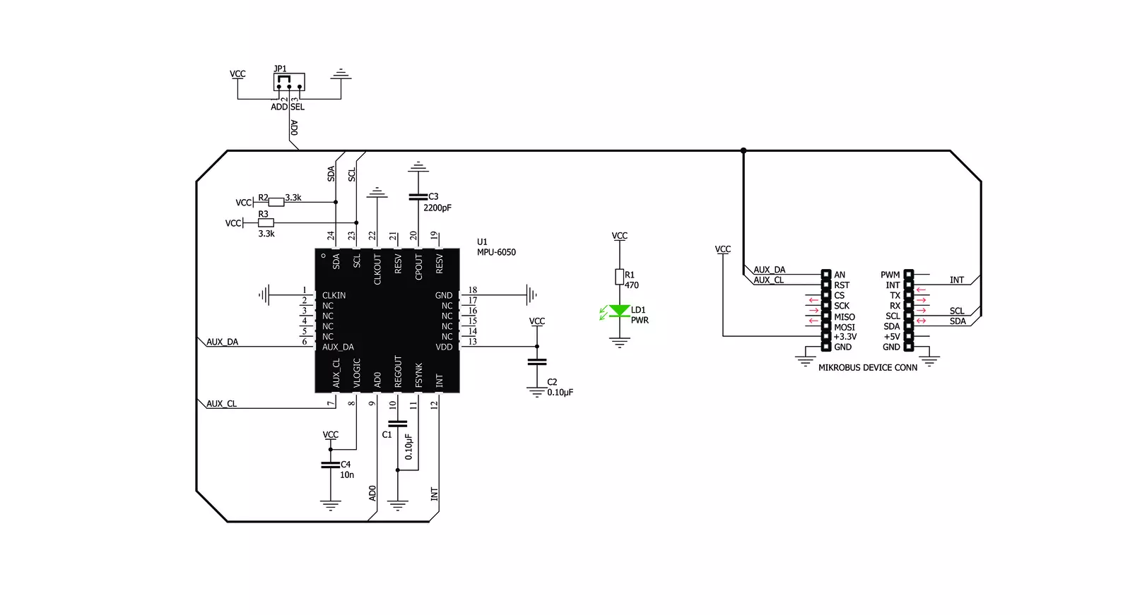
Accel 8 Click is based on the MPU6050, a motion tracking sensor IC, from TDK Invensense. It is an advanced, integrated microelectromechanical gyroscope and accelerometer sensor (MEMS), combined with the powerful data processing engine. There is a respective accelerometer or gyroscope MEMS on each axis. The output of each MEMS is processed and digitized by a separate sigma-delta 16-bit A/D converter (ADC). The outputs can be processed by a programmable low-pass filter, while their sample rate can be selected by the user. Three-axis gyroscope MEMS can be programmed to measure the rotation about each axis, in four different ranges of rotational speed (degrees per angle, DPS): ±250, ±500, ±1000, and ±2000. Three-axis accelerometer MEMS can be programmed to measure the acceleration along each axis, in four different acceleration ranges: ±2g, ±4g, ±8g, and ±16g. The user can select an optimal range for both properties, depending on the application requirements. The embedded Digital Motion Processor™ can process complex 6-axis motion detection and gesture recognition algorithms without taking up processing cycles of the host microcontroller (MCU), making it perfectly suited
for different kinds of low-power applications. The DMP engine offers a high output data rate (ODR), improving measurement accuracy. Due to DMP hardware-accelerated motion detection algorithms, MPU60x0 are very popular motion tracking ICs and there are many different designs using both MPU6050 and MPU6000 (e.g. MPU IMU click). Unlike the MPU6000, the MPU6050 uses the I2C communication interface. MPU6050 incorporates a powerful programmable interrupt engine. The interrupt engine can generate a signal on the interrupt pin for several interrupt sources, including FIFO Buffer overflow, Data Ready, I2C Master Error, and I2C Slave Error. The interrupt is routed to the INT pin of the mikroBUS™. A FIFO buffer helps to further reduce the processing load, offering temporary storage for the output data. The MPU6050 features a FIFO buffer with the capacity of 1024 bytes. The user can select which data will be stored in the FIFO buffer: gyro data, accel data, temperature readings, and auxiliary sensor readings. Once the FIFO buffer is full, it will start discarding the oldest data, allowing new data to be written. The FIFO buffer overflow condition can be used to trigger an interrupt, alerting the host MCU about its status. Another powerful
feature of the MPU6050 is its ability to be interfaced with an additional sensor, such as the 3-axis compass. By utilizing the MotionFusion™ firmware on the chip, along with the run-time calibration, it offers the complete 9-axis motion sensing solution. This sensor can be connected to the auxiliary I2C pins, routed to the mikroBUS™. Aux I2C clock pin is routed to the RST pin of the mikroBUS™ and it is labeled as CL, while the Aux I2C data pin is routed to the AN pin of the mikroBUS™, labeled as DA. Besides the compass sensor, other general-purpose sensors that use I2C interface can be connected, too. An interrupt can be generated if there is an error in the communication between the MPU6050 and the auxiliary sensor. The I2C address of the MPU6050 can be selected by the ADD SEL jumper. This SMD jumper is used to select the least significant bit (LSB) of the 7-bit I2C address. The value of the LSB is decided by the position of this jumper. Accel 8 click uses the I2C communication interface. It has pull-up resistors connected to the mikroBUS™ 3.3V rail. Proper conversion of logic voltage levels should be applied before the Click board™ is used with MCUs operated with 5V.


Features overview
Development board
UNI-DS v8 is a development board specially designed for the needs of rapid development of embedded applications. It supports a wide range of microcontrollers, such as different STM32, Kinetis, TIVA, CEC, MSP, PIC, dsPIC, PIC32, and AVR MCUs regardless of their number of pins, and a broad set of unique functions, such as the first-ever embedded debugger/programmer over WiFi. The development board is well organized and designed so that the end-user has all the necessary elements, such as switches, buttons, indicators, connectors, and others, in one place. Thanks to innovative manufacturing technology, UNI-DS v8 provides a fluid and immersive working experience, allowing access anywhere and under any
circumstances at any time. Each part of the UNI-DS v8 development board contains the components necessary for the most efficient operation of the same board. An advanced integrated CODEGRIP programmer/debugger module offers many valuable programming/debugging options, including support for JTAG, SWD, and SWO Trace (Single Wire Output)), and seamless integration with the Mikroe software environment. Besides, it also includes a clean and regulated power supply module for the development board. It can use a wide range of external power sources, including a battery, an external 12V power supply, and a power source via the USB Type-C (USB-C) connector. Communication options such as USB-UART, USB
HOST/DEVICE, CAN (on the MCU card, if supported), and Ethernet is also included. In addition, it also has the well-established mikroBUS™ standard, a standardized socket for the MCU card (SiBRAIN standard), and two display options for the TFT board line of products and character-based LCD. UNI-DS v8 is an integral part of the Mikroe ecosystem for rapid development. Natively supported by Mikroe software tools, it covers many aspects of prototyping and development thanks to a considerable number of different Click boards™ (over a thousand boards), the number of which is growing every day.

Microcontroller Overview
MCU Card / MCU
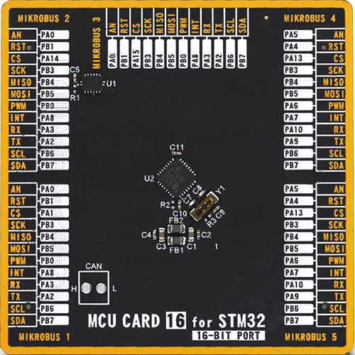
Type
8th Generation
Architecture
ARM Cortex-M4
MCU Memory (KB)
256
Silicon Vendor
STMicroelectronics
Pin count
32
RAM (Bytes)
65536
Used MCU Pins
mikroBUS™ mapper
Take a closer look
Click board™ Schematic
Step by step
Project assembly

Start by selecting your development board and Click board™. Begin with the UNI-DS v8 as your development board.


Software Support
Library Description
This library contains API for Accel 8 Click driver.
Key functions:
accel8_get_accel_axis- This function reads Accel axis dataaccel8_get_gyro_axis- This function reads Gyro axis dataaccel8_get_interrupt- This function returns Interupt state
Open Source
Code example
The complete application code and a ready-to-use project are available through the NECTO Studio Package Manager for direct installation in the NECTO Studio. The application code can also be found on the MIKROE GitHub account.
/*!
 * \file
 * \brief Accel8 Click example
 *
 * # Description
 * This application measures accelermeter and gyroscopic data and temperature.
 *
 * The demo application is composed of two sections :
 *
 * ## Application Init
 * Initialization driver init, reset chip and start configuration chip for measurement.
 *
 * ## Application Task
 * Reads Accel X/Y/Z axis, Gyro X/Y/Z axis and device Temperature.
 * All data logs on the USBUART every 2 sec.
 *
 * \author MikroE Team
 *
 */
// ------------------------------------------------------------------- INCLUDES

#include "board.h"
#include "log.h"
#include "accel8.h"

// ------------------------------------------------------------------ VARIABLES

static accel8_t accel8;
static log_t logger;
static range_retval_t range;

// ------------------------------------------------------ APPLICATION FUNCTIONS

void application_init ( void )
{
    log_cfg_t log_cfg;
    accel8_cfg_t cfg;

    uint8_t temp_write;

    /**
     * Logger initialization.
     * Default baud rate: 115200
     * Default log level: LOG_LEVEL_DEBUG
     * @note If USB_UART_RX and USB_UART_TX
     * are defined as HAL_PIN_NC, you will
     * need to define them manually for log to work.
     * See @b LOG_MAP_USB_UART macro definition for detailed explanation.
     */
    LOG_MAP_USB_UART( log_cfg );
    log_init( &logger, &log_cfg );
    log_info( &logger, "---- Application Init ----" );

    //  Click initialization.

    accel8_cfg_setup( &cfg );
    ACCEL8_MAP_MIKROBUS( cfg, MIKROBUS_1 );
    temp_write = accel8_init( &accel8, &cfg );

	if ( temp_write ==  ACCEL8_INIT_ERROR )
	{
		log_info( &logger, "ERROR\r\n" );
		for ( ; ; );
	}

    log_printf( &logger, " *-* Device Reset *-* \r\n");
    temp_write = ACCEL8_PM1_DEVICE_RESET;
    accel8_generic_write( &accel8, ACCEL8_REG_PWR_MGMT_1, &temp_write, 1 );
    Delay_ms ( 500 );
    temp_write = ACCEL8_GYRO_RESET | ACCEL8_ACCEL_RESET | ACCEL8_TEMP_RESET;
    accel8_generic_write( &accel8, ACCEL8_REG_SIGNAL_PATH_RESET, &temp_write, 1 );
	Delay_ms ( 500 );
    log_printf( &logger, " *-* Device Configuration *-* \r\n" );
    accel8_default_cfg ( &accel8, ACCEL8_ACCEL_CFG_FULL_SCALE_RANGE_2g, ACCEL8_GYRO_CFG_FULL_SCALE_RANGE_250dbs, &range);

    Delay_ms ( 1000 );
    log_printf( &logger, " --- Start Measurement --- \r\n" );Delay_ms ( 100 );
}

void application_task ( void )
{
    float temperature;
    int16_t x_gyro_axis;
    int16_t y_gyro_axis;
    int16_t z_gyro_axis;
    int16_t x_accel_axis;
    int16_t y_accel_axis;
    int16_t z_accel_axis;

    //  Task implementation.

    accel8_get_accel_axis( &accel8,&x_accel_axis, &y_accel_axis, &z_accel_axis );
    accel8_get_gyro_axis( &accel8, &x_gyro_axis, &y_gyro_axis , &z_gyro_axis );
    temperature = accel8_get_temperature( &accel8 );

    // LOGS DATA

    log_printf( &logger, "________________ Accel 8 Click _________\r\n" );
    log_printf( &logger, "|  Data   | X axis | Y axis | Z axis |  Range  |\r\n" );
    log_printf( &logger, "|______|______|______|_____|________|\r\n" );
    log_printf( &logger, "|  Accel  | %d    | %d    | %d    | %dg    |\r\n", x_accel_axis, y_accel_axis, z_accel_axis, &range.accel_range );
    log_printf( &logger, "|_______|______|_____|_______|_______|\r\n" );
    log_printf( &logger, "|  Gyro    | %d     | %d     | %d     | %ddps   |\r\n", x_gyro_axis, y_gyro_axis, z_gyro_axis, &range.gyro_range );
    log_printf( &logger, "|_______|_______|______|______|________|\r\n" );
    log_printf( &logger, "|  Temp   | %.2f  C         |\r\n" , temperature);
    log_printf( &logger, "|_______|____________|\r\n" );

    log_printf( &logger, " \r\n" );
    Delay_ms ( 1000 );
    Delay_ms ( 1000 );
}

int main ( void )
{
    /* Do not remove this line or clock might not be set correctly. */
    #ifdef PREINIT_SUPPORTED
    preinit();
    #endif

    application_init( );

    for ( ; ; )
    {
        application_task( );
    }

    return 0;
}


// ------------------------------------------------------------------------ END


