Detect falls and impacts easily with MXC62320MP and TM4C129XNCZAD
Making sense of motion: The magic of accelerometers

Published Oct 05, 2023
Click board™
Accel 17 Click
Dev. board
Fusion for ARM v8
Compiler
NECTO Studio
MCU
TM4C129XNCZAD
This solution is invaluable for measuring and analyzing changes in velocity and acceleration, providing essential data for a wide range of purposes
A
A
Hardware Overview
How does it work?
Accel 17 Click is based on the MXC62320MP, a complete dual-axis acceleration measurement system fabricated on a monolithic CMOS process from MEMSIC. The MXC62320MP operation is based on heat transfer by natural convection and operates like other accelerometers, except it is a gas in the MEMSIC sensor. It can measure dynamic acceleration (e.g., vibration) and static acceleration (e.g., gravity), with full-scale acceleration measurements ranging from ±2g. It also comes with embedded Power Up/Down and self-test function, resolution better than 1mg, and >50.000g shock survival rating. In addition to all
these features, it also has excellent temperature stability and low power consumption/low active current. This accelerometer can enter a Power-Down mode by writing a command [xxxxxxx1] into the accelerometer’s internal register, while a Wake-Up operation is performed when a command of [xxxxxxx0] is written into the same register. Note that the MXC62320MP needs about 75ms (typical) for Power-Up time. Accel 17 Click communicates with MCU using a standard I2C 2-Wire interface that supports 400kHz Fast Mode operation. Since the sensor for operation requires a 3.3V logic voltage level only, this Click board™
also features the PCA9306 voltage-level translator from Texas Instruments. The I2C interface bus lines are routed to the dual bidirectional voltage-level translator, allowing this Click board™ to work properly with both 3.3V and 5V MCUs. This Click board™ can operate with either 3.3V or 5V logic voltage levels selected via the VIO SEL jumper. This way, both 3.3V and 5V capable MCUs can use the communication lines properly. Also, this Click board™ comes equipped with a library containing easy-to-use functions and an example code that can be used as a reference for further development.


Features overview
Development board
Fusion for ARM v8 is a development board specially designed for the needs of rapid development of embedded applications. It supports a wide range of microcontrollers, such as different ARM® Cortex®-M based MCUs regardless of their number of pins, and a broad set of unique functions, such as the first-ever embedded debugger/programmer over WiFi. The development board is well organized and designed so that the end-user has all the necessary elements, such as switches, buttons, indicators, connectors, and others, in one place. Thanks to innovative manufacturing technology, Fusion for ARM v8 provides a fluid and immersive working experience, allowing access anywhere and under any
circumstances at any time. Each part of the Fusion for ARM v8 development board contains the components necessary for the most efficient operation of the same board. An advanced integrated CODEGRIP programmer/debugger module offers many valuable programming/debugging options, including support for JTAG, SWD, and SWO Trace (Single Wire Output)), and seamless integration with the Mikroe software environment. Besides, it also includes a clean and regulated power supply module for the development board. It can use a wide range of external power sources, including a battery, an external 12V power supply, and a power source via the USB Type-C (USB-C) connector.
Communication options such as USB-UART, USB HOST/DEVICE, CAN (on the MCU card, if supported), and Ethernet is also included. In addition, it also has the well-established mikroBUS™ standard, a standardized socket for the MCU card (SiBRAIN standard), and two display options for the TFT board line of products and character-based LCD. Fusion for ARM v8 is an integral part of the Mikroe ecosystem for rapid development. Natively supported by Mikroe software tools, it covers many aspects of prototyping and development thanks to a considerable number of different Click boards™ (over a thousand boards), the number of which is growing every day.

Microcontroller Overview
MCU Card / MCU
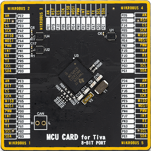
Type
8th Generation
Architecture
ARM Cortex-M4
MCU Memory (KB)
1024
Silicon Vendor
Texas Instruments
Pin count
212
RAM (Bytes)
262144
Used MCU Pins
mikroBUS™ mapper
Take a closer look
Click board™ Schematic

Step by step
Project assembly

Start by selecting your development board and Click board™. Begin with the Fusion for ARM v8 as your development board.


Software Support
Library Description
This library contains API for Accel 17 Click driver.
Key functions:
accel17_get_axes_data- Accel data readingaccel17_generic_read- Reading functionaccel17_generic_write- Writing function
Open Source
Code example
The complete application code and a ready-to-use project are available through the NECTO Studio Package Manager for direct installation in the NECTO Studio. The application code can also be found on the MIKROE GitHub account.
/*!
 * @file main.c
 * @brief Accel17 Click example
 *
 * # Description
 * This example showcases ability of the device to read
 * x, y axis orientation.
 *
 * The demo application is composed of two sections :
 *
 * ## Application Init
 * Initialization of communication modules(I2C, UART), and
 * configures device.
 *
 * ## Application Task
 * Reads axis data and calculates it and logs result every 300ms.
 *
 * @author Luka Filipovic
 *
 */

#include "board.h"
#include "log.h"
#include "accel17.h"

static accel17_t accel17;
static log_t logger;

void application_init ( void )
{
    log_cfg_t log_cfg;  /**< Logger config object. */
    accel17_cfg_t accel17_cfg;  /**< Click config object. */

    /**
     * Logger initialization.
     * Default baud rate: 115200
     * Default log level: LOG_LEVEL_DEBUG
     * @note If USB_UART_RX and USB_UART_TX
     * are defined as HAL_PIN_NC, you will
     * need to define them manually for log to work.
     * See @b LOG_MAP_USB_UART macro definition for detailed explanation.
     */
    LOG_MAP_USB_UART( log_cfg );
    log_init( &logger, &log_cfg );
    log_info( &logger, " Application Init " );

    // Click initialization.
    accel17_cfg_setup( &accel17_cfg );
    ACCEL17_MAP_MIKROBUS( accel17_cfg, MIKROBUS_1 );
    err_t init_flag = accel17_init( &accel17, &accel17_cfg );
    if ( I2C_MASTER_ERROR == init_flag )
    {
        log_error( &logger, " Application Init Error. " );
        log_info( &logger, " Please, run program again... " );

        for ( ; ; );
    }

    accel17_default_cfg ( &accel17 );
    Delay_ms ( 1000 );
    log_info( &logger, " Application Task " );
}

void application_task ( void )
{
    accel17_axes_t axes;
    accel17_get_axes_data ( &accel17, &axes );
    log_printf( &logger, " > X[degree]: %.2f\r\n > Y[degree]: %.2f\r\n", axes.x, axes.y );
    log_printf( &logger, "*********************************\r\n" );
    Delay_ms ( 300 );
}

int main ( void )
{
    /* Do not remove this line or clock might not be set correctly. */
    #ifdef PREINIT_SUPPORTED
    preinit();
    #endif

    application_init( );

    for ( ; ; )
    {
        application_task( );
    }

    return 0;
}

// ------------------------------------------------------------------------ END
Additional Support
Resources
Category:Motion


