Improve your understanding of dynamic environments with NJR4265RF2C1 and STM32F302VC
Your every move matters: Microwave Doppler detection for a smarter world

Published Oct 05, 2023
Click board™
Microwave 2 click (for EU)
Dev. board
Fusion for STM32 v8
Compiler
NECTO Studio
MCU
STM32F302VC
This solution lays the foundation for smart, interconnected ecosystems where objects, devices, and environments seamlessly respond to human movement and proximity
A
A
Hardware Overview
How does it work?
Microwave 2 Click is based on the NJR4265RF2C1, an intelligent 24GHz microwave motion sensor from JRC. The onboard microwave motion sensor is based on the Doppler effect. It transmits waves and picks them back as they get reflected from a moving object. According to Doppler effect principle, the movement of an object relative to the position of the listener (sensor in this case), causes the reflected waves to increase their frequency when the object approaches, or decrease their frequency as the object moves away (leaves). Comparing the reflected waves with the base frequency at which the waves are transmitted can reveal the object movement properties. The integrated MCU of the NJR4265RF2C1 module processes the signal reduces the noise and enhances the useful signal, allowing reliable detection and steady sensing of the movement. It then makes a movement direction decision, based on the collected data and signals it back to the host MCU. Two LEDs, labeled as DL (green) and DA (yellow) are routed to the dedicated module pins, labeled as DETECT APPROACHING and DETECT LEAVING. These pins will signal the corresponding events when they
are detected by the sensor. The pins are also routed to the mikroBUS™ AN and INT pins respectively labeled as DA and DL on the Click board™. This way, the movement detection events can be signaled to the host MCU, too. The NJR4265RF2C1 module is able to sense moving objects up to 10m in front of the sensor. The detection cone is about ±35° in respect to the central perpendicular axis of the sensor. The object motion speed should be in the range between 0.25 m/s to 1 m/s. The frequency stability of the emitted waves is in the range of 1MHz below, and up to the center frequency of 24.15 to 24.25 GHz, over the temperature range from -20 °C to +60 °C, allowing steady and accurate detection in various conditions. Wave reflections caused by random objects like leaves, air movement, insects, and other similar objects, is suppressed by the on-chip integrated MCU, increasing the target object detection reliability. However, due to its nature, the noise suppression algorithm limits the detectable object speed and size, which sometimes can be undesirable. Having in mind these limitations, the module is best used in applications where larger, slow-moving objects detection is required, such as
the pedestrian movement applications, human or animal detection applications, and similar. The host MCU can communicate with the Microwave 2 click using the UART interface. The NJR4265RF2C1 module has its UART pins routed to the RX and TX pins of the mikroBUS™. The UART communication parameters are fixed to 9600 bps, 8 data bits, no parity, and one stop bit (9600, 8, N, 1). The MCU can use the UART commands to set the detection thresholds, set the sensor mode, perform acquisition of the detection results and other sensor data. The NJR4265RF2C1 module datasheet offers a list of UART commands, with the detailed explanation of each. However, Microwave 2 click is supplied with the library compatible with all the MikroE compilers, offering a set of functions for simplified control and rapid development of custom applications. Microwave 2 click can be interfaced with both 3.3V and 5V MCUs. To select the appropriate operating voltage of the module, the SMD jumper labeled as the PWR SEL can be moved to the desired voltage position, clearly labeled underneath the jumper itself.


Features overview
Development board
Fusion for STM32 v8 is a development board specially designed for the needs of rapid development of embedded applications. It supports a wide range of microcontrollers, such as different 32-bit ARM® Cortex®-M based MCUs from STMicroelectronics, regardless of their number of pins, and a broad set of unique functions, such as the first-ever embedded debugger/programmer over WiFi. The development board is well organized and designed so that the end-user has all the necessary elements, such as switches, buttons, indicators, connectors, and others, in one place. Thanks to innovative manufacturing technology, Fusion for STM32 v8 provides a fluid and immersive working experience, allowing
access anywhere and under any circumstances at any time. Each part of the Fusion for STM32 v8 development board contains the components necessary for the most efficient operation of the same board. An advanced integrated CODEGRIP programmer/debugger module offers many valuable programming/debugging options, including support for JTAG, SWD, and SWO Trace (Single Wire Output)), and seamless integration with the Mikroe software environment. Besides, it also includes a clean and regulated power supply module for the development board. It can use a wide range of external power sources, including a battery, an external 12V power supply, and a power source via the USB Type-C (USB-C) connector.
Communication options such as USB-UART, USB HOST/DEVICE, CAN (on the MCU card, if supported), and Ethernet is also included. In addition, it also has the well-established mikroBUS™ standard, a standardized socket for the MCU card (SiBRAIN standard), and two display options for the TFT board line of products and character-based LCD. Fusion for STM32 v8 is an integral part of the Mikroe ecosystem for rapid development. Natively supported by Mikroe software tools, it covers many aspects of prototyping and development thanks to a considerable number of different Click boards™ (over a thousand boards), the number of which is growing every day.

Microcontroller Overview
MCU Card / MCU
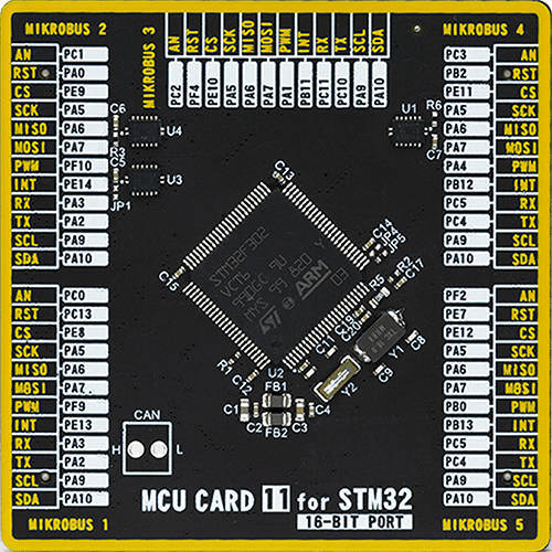
Type
8th Generation
Architecture
ARM Cortex-M4
MCU Memory (KB)
256
Silicon Vendor
STMicroelectronics
Pin count
100
RAM (Bytes)
40960
Used MCU Pins
mikroBUS™ mapper
Take a closer look
Click board™ Schematic

Step by step
Project assembly

Start by selecting your development board and Click board™. Begin with the Fusion for STM32 v8 as your development board.


Software Support
Library Description
This library contains API for Microwave 2 (for EU) Click driver.
Key functions:
microwave2_dl_state- Set pin DLmicrowave2_da_state- Set pin DA
Open Source
Code example
The complete application code and a ready-to-use project are available through the NECTO Studio Package Manager for direct installation in the NECTO Studio. The application code can also be found on the MIKROE GitHub account.
/*!
* \file
* \brief Microwave2 Click example
*
* # Description
* This application is an accurate and reliable short to medium range motion detection.
*
* The demo application is composed of two sections :
*
* ## Application Init
* Initializes the Click board for communication.
*
* ## Application Task
* Data sent from the Click board is captured and different actions are applied.
*
* \author MikroE Team
*
*/
// ------------------------------------------------------------------- INCLUDES
#include "board.h"
#include "log.h"
#include "microwave2.h"
#include "string.h"
#define PROCESS_COUNTER 10
#define PROCESS_RX_BUFFER_SIZE 500
#define PROCESS_PARSER_BUFFER_SIZE 500
// ------------------------------------------------------------------ VARIABLES
static microwave2_t microwave2;
static log_t logger;
static char current_parser_buf[ PROCESS_PARSER_BUFFER_SIZE ];
// ------------------------------------------------------- ADDITIONAL FUNCTIONS
static void microwave2_parser ( char * buffer )
{
for ( uint16_t cnt = 0; cnt < sizeof( buffer ); cnt++ )
{
if ( buffer[ cnt ] == '@' )
{
if ( buffer[ cnt+1 ] == 'C' ) {
log_printf( &logger, "Approaching \r\n" );
}
if ( buffer[ cnt+1 ] == 'L' ) {
log_printf( &logger, "Moving away \r\n" );
}
if ( buffer[ cnt+1 ] == 'N' ) {
log_printf( &logger, "No movement \r\n");
}
}
}
}
static void microwave2_process ( void )
{
int32_t rsp_size;
uint16_t rsp_cnt = 0;
char uart_rx_buffer[ PROCESS_RX_BUFFER_SIZE ] = { 0 };
uint16_t check_buf_cnt;
uint8_t process_cnt = PROCESS_COUNTER;
// Clear parser buffer
memset( current_parser_buf, 0 , PROCESS_PARSER_BUFFER_SIZE );
while( process_cnt != 0 )
{
rsp_size = microwave2_generic_read( µwave2, &uart_rx_buffer, PROCESS_RX_BUFFER_SIZE );
if ( rsp_size > 0 )
{
// Validation of the received data
for ( check_buf_cnt = 0; check_buf_cnt < rsp_size; check_buf_cnt++ )
{
if ( uart_rx_buffer[ check_buf_cnt ] == 0 )
{
uart_rx_buffer[ check_buf_cnt ] = 13;
}
}
// Storages data in parser buffer
rsp_cnt += rsp_size;
if ( rsp_cnt < PROCESS_PARSER_BUFFER_SIZE )
{
strncat( current_parser_buf, uart_rx_buffer, rsp_size );
}
// Clear RX buffer
memset( uart_rx_buffer, 0, PROCESS_RX_BUFFER_SIZE );
}
else
{
process_cnt--;
// Process delay
Delay_10ms( );
}
}
microwave2_parser(current_parser_buf);
}
// ------------------------------------------------------ APPLICATION FUNCTIONS
void application_init ( void )
{
log_cfg_t log_cfg;
microwave2_cfg_t cfg;
/**
* Logger initialization.
* Default baud rate: 115200
* Default log level: LOG_LEVEL_DEBUG
* @note If USB_UART_RX and USB_UART_TX
* are defined as HAL_PIN_NC, you will
* need to define them manually for log to work.
* See @b LOG_MAP_USB_UART macro definition for detailed explanation.
*/
LOG_MAP_USB_UART( log_cfg );
log_init( &logger, &log_cfg );
log_info( &logger, "---- Application Init ----" );
// Click initialization.
microwave2_cfg_setup( &cfg );
MICROWAVE2_MAP_MIKROBUS( cfg, MIKROBUS_1 );
microwave2_init( µwave2, &cfg );
}
void application_task ( void )
{
microwave2_process();
}
int main ( void )
{
/* Do not remove this line or clock might not be set correctly. */
#ifdef PREINIT_SUPPORTED
preinit();
#endif
application_init( );
for ( ; ; )
{
application_task( );
}
return 0;
}
// ------------------------------------------------------------------------ END
Additional Support
Resources
Category:Motion


