Set, track, and achieve your wellness milestones easily with STP201M and STM32F091RC
Step by step to success: Pedometer magic in your hand

Published Oct 05, 2023
Click board™
Pedometer Click
Dev. board
Fusion for STM32 v8
Compiler
NECTO Studio
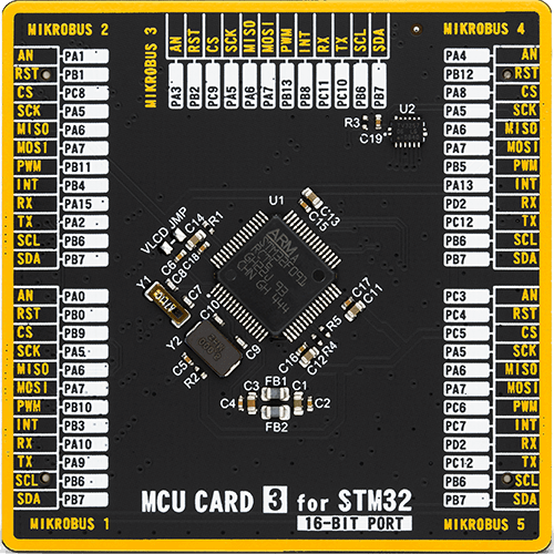
MCU
STM32F091RC
Our pedometer is your reliable companion for tracking daily steps, empowering you to achieve your fitness goals with precision
A
A
Hardware Overview
How does it work?
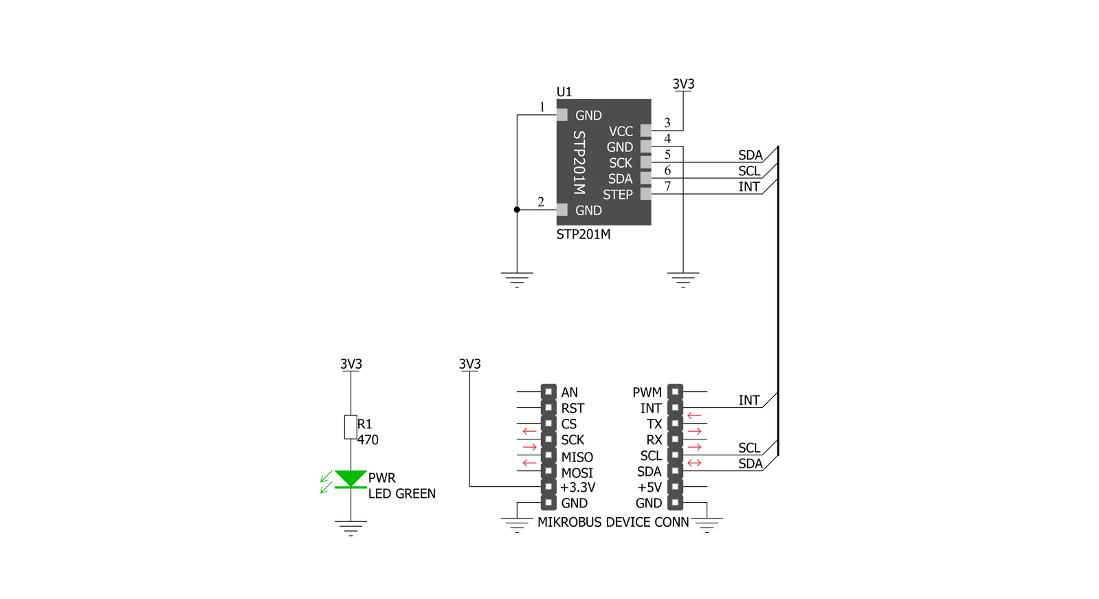
Pedometer Click is based on the STP201M, a 3D pedometer module with an IC chipset from NiceRF. The module itself is designed for wrist pedometer products, like the pedometer bracelet or watch for example. The end user doesn’t have to worry about doing any calculations on their own, or worry about what the algorithm for step detection is doing, since the INT pins output is already a measurement of the steps that were taken. Specifically, a MEMS sensor. Micro-electro-mechanical system sensors, abbreviated to MEMS, are made out of very small components, with their size usually ranging from 1 to 100 micrometers. These account for the sensor being very small and therefore it having low energy consumption and
also not requiring a lot of space. This particular sensor is a 3D one. The three axes it utilizes, allow for precise measurements of any movement and the direction its taking. The three axes system, along with the MCUs meticulous algorithm, make it significantly less likely to make any false-positive counts (ex. tying up shoes). The MCU has two distinguished modes. The first one of them is the operational mode. The MCU is designed to go into the operational mode whenever it senses some activity. However, if there is no discernible movement over the course of 20 seconds, it goes into the sleep mode. This mode is characterized by the very low energy consumption of only 5 μA max. The STP201M modules communication is
somewhat different from the standard I2C protocol. Since our libraries do not support it, the user has the capability of changing the code of the main MCU in order to fit the protocol of the module and thus change any preprogramed settings. Since the modules maximum operatin voltage is 3.6V, the Pedometer click uses the 3.3V rail for power supply. The other pins it utilizes are the, before mentioned, Interrupt pin, and the I2C Clock and Data pins. This click also has a Power LED indicator. This Click Board™ is designed to be operated only with 3.3V logic level. A proper logic voltage level conversion should be performed before the Click board™ is used with MCUs with logic levels of 5V.


Features overview
Development board
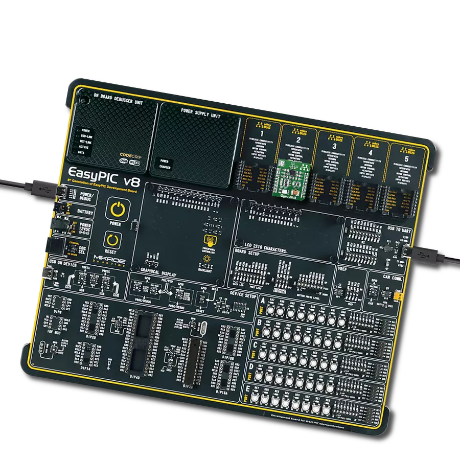
Fusion for STM32 v8 is a development board specially designed for the needs of rapid development of embedded applications. It supports a wide range of microcontrollers, such as different 32-bit ARM® Cortex®-M based MCUs from STMicroelectronics, regardless of their number of pins, and a broad set of unique functions, such as the first-ever embedded debugger/programmer over WiFi. The development board is well organized and designed so that the end-user has all the necessary elements, such as switches, buttons, indicators, connectors, and others, in one place. Thanks to innovative manufacturing technology, Fusion for STM32 v8 provides a fluid and immersive working experience, allowing
access anywhere and under any circumstances at any time. Each part of the Fusion for STM32 v8 development board contains the components necessary for the most efficient operation of the same board. An advanced integrated CODEGRIP programmer/debugger module offers many valuable programming/debugging options, including support for JTAG, SWD, and SWO Trace (Single Wire Output)), and seamless integration with the Mikroe software environment. Besides, it also includes a clean and regulated power supply module for the development board. It can use a wide range of external power sources, including a battery, an external 12V power supply, and a power source via the USB Type-C (USB-C) connector.
Communication options such as USB-UART, USB HOST/DEVICE, CAN (on the MCU card, if supported), and Ethernet is also included. In addition, it also has the well-established mikroBUS™ standard, a standardized socket for the MCU card (SiBRAIN standard), and two display options for the TFT board line of products and character-based LCD. Fusion for STM32 v8 is an integral part of the Mikroe ecosystem for rapid development. Natively supported by Mikroe software tools, it covers many aspects of prototyping and development thanks to a considerable number of different Click boards™ (over a thousand boards), the number of which is growing every day.

Microcontroller Overview
MCU Card / MCU
Type
8th Generation
Architecture
ARM Cortex-M0
MCU Memory (KB)
256
Silicon Vendor
STMicroelectronics
Pin count
64
RAM (Bytes)
32768
Used MCU Pins
mikroBUS™ mapper
Take a closer look
Click board™ Schematic
Step by step
Project assembly

Start by selecting your development board and Click board™. Begin with the Fusion for STM32 v8 as your development board.


Track your results in real time
Application Output
1. Application Output - In Debug mode, the 'Application Output' window enables real-time data monitoring, offering direct insight into execution results. Ensure proper data display by configuring the environment correctly using the provided tutorial.

2. UART Terminal - Use the UART Terminal to monitor data transmission via a USB to UART converter, allowing direct communication between the Click board™ and your development system. Configure the baud rate and other serial settings according to your project's requirements to ensure proper functionality. For step-by-step setup instructions, refer to the provided tutorial.

3. Plot Output - The Plot feature offers a powerful way to visualize real-time sensor data, enabling trend analysis, debugging, and comparison of multiple data points. To set it up correctly, follow the provided tutorial, which includes a step-by-step example of using the Plot feature to display Click board™ readings. To use the Plot feature in your code, use the function: plot(*insert_graph_name*, variable_name);. This is a general format, and it is up to the user to replace 'insert_graph_name' with the actual graph name and 'variable_name' with the parameter to be displayed.

Software Support
Library Description
This library contains API for Pedometer Click driver.
Key functions:
pedometer_get_interrupt_state- Functions for get Interrupt state on the INT pinpedometer_get_step_counter- Functions for get step counterpedometer_generic_read- Generic read function
Open Source
Code example
The complete application code and a ready-to-use project are available through the NECTO Studio Package Manager for direct installation in the NECTO Studio. The application code can also be found on the MIKROE GitHub account.
/*!
 * \file
 * \brief Pedometer Click example
 *
 * # Description
 * This application detected steps.
 *
 * The demo application is composed of two sections :
 *
 * ## Application Init
 * Initializes driver init and sets step counter on 0.
 *
 * ## Application Task
 * It checks if a new step is detected, if detected new step -
 * reads the current number of steps made and logs data to the USBUART.
 *
 * \author MikroE Team
 *
 */
// ------------------------------------------------------------------- INCLUDES

#include "board.h"
#include "log.h"
#include "pedometer.h"

// ------------------------------------------------------------------ VARIABLES

static pedometer_t pedometer;
static log_t logger;

// ------------------------------------------------------ APPLICATION FUNCTIONS

void application_init ( void )
{
    log_cfg_t log_cfg;
    pedometer_cfg_t cfg;

    /**
     * Logger initialization.
     * Default baud rate: 115200
     * Default log level: LOG_LEVEL_DEBUG
     * @note If USB_UART_RX and USB_UART_TX
     * are defined as HAL_PIN_NC, you will
     * need to define them manually for log to work.
     * See @b LOG_MAP_USB_UART macro definition for detailed explanation.
     */
    LOG_MAP_USB_UART( log_cfg );
    log_init( &logger, &log_cfg );
    log_info(&logger, "---- Application Init ----");

    //  Click initialization.

    pedometer_cfg_setup( &cfg );
    PEDOMETER_MAP_MIKROBUS( cfg, MIKROBUS_1 );
    pedometer_init( &pedometer, &cfg );
}

void application_task ( void )
{
    //  Task implementation.

    uint8_t new_step;
    uint32_t s_counter;
    char demoText[ 50 ];

    new_step = pedometer_process( &pedometer );

    if ( new_step == PEDOMETER_NEW_STEP_DETECTED )
    {
        s_counter = pedometer_get_step_counter( &pedometer );
        log_printf( &logger, " Step Counter : %d \r\n ", s_counter );

        Delay_ms ( 50 );
    }

}

int main ( void )
{
    /* Do not remove this line or clock might not be set correctly. */
    #ifdef PREINIT_SUPPORTED
    preinit();
    #endif

    application_init( );

    for ( ; ; )
    {
        application_task( );
    }

    return 0;
}


// ------------------------------------------------------------------------ END
Additional Support
Resources
Category:Motion