Seize control and dominate the motion of your BLDC with STSPIN233 and MKV58F1M0VLQ24
Experience the future of motor control

Published Jul 26, 2023
Click board™
STSPIN233 Click
Dev. board
Fusion for Kinetis v8
Compiler
NECTO Studio
MCU
MKV58F1M0VLQ24
Experience enhanced responsiveness and accuracy with our advanced brushless motor control, perfect for robotics, drones, and industrial automation
A
A
Hardware Overview
How does it work?
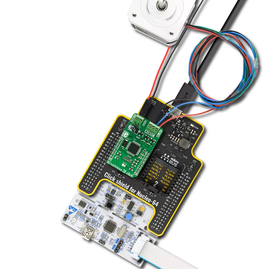
STSPIN233 Click is based on the STSPIN233, a low voltage 3-phase integrated motor driver from STMicroelectronics. It contains three independent H-Bridges, each controlling one phase of the brushless motor. These integrated H-Bridges are very efficient - with an ON resistance of approximately 400mΩ (HS+LS) across each bridge. These features make STSPIN233 click perfectly suited for the rapid development of various battery-powered stepper motor applications, including toys, printers, mechatronics, drones, robotics-related applications, and more. Besides the brushless driver IC, this Click board™ also has STM32F031K6T6 MCU onboard, which serves as a “brain” of the STSPIN233 Click. It comes with preloaded firmware, which is programmed to take
control of the motor driver. It reads the current motor status and signals from an optional rotary encoder, calculates desired and real motor status values in real time, and makes necessary corrections to the motor driver. The motor can be controlled using RST, INT, and UART pins – RX and TX. That way, a very reliable brushless motor driver is achieved. The RST pin of the STSPIN233 Click is used to set both bridge outputs in the HIGH-Z mod, disconnecting the power supply from the H-Bridges. This pin allows lower average power consumption as no current can flow from the power supply to the motor. This pin is routed to the RST pin of the mikroBUS™. The INT pin has a double purpose: when set to a high logic level, it acts as a chip enable, allowing the device to
operate. In the case of a fault condition on the IC, it will be asserted to a LOW logic level, acting as an interrupt pin. A restart attempt will be made after a timeout period defined by the external capacitor and resistor values. This pin is routed to both INT pins of the mikroBUS™, allowing the host MCU to use both functions. The mentioned pin is labeled as FLT on the Click board™ respectively. The motor power supply can be connected to the input terminal labeled as VIN and should be within the range of 1.8V to 10V. Brushless motor coils can be connected to U, V, and W terminals. The Click board™ requires an external power supply for the motor to work. However, it also requires 3.3V from the mikroBUS™ rail.

Features overview
Development board
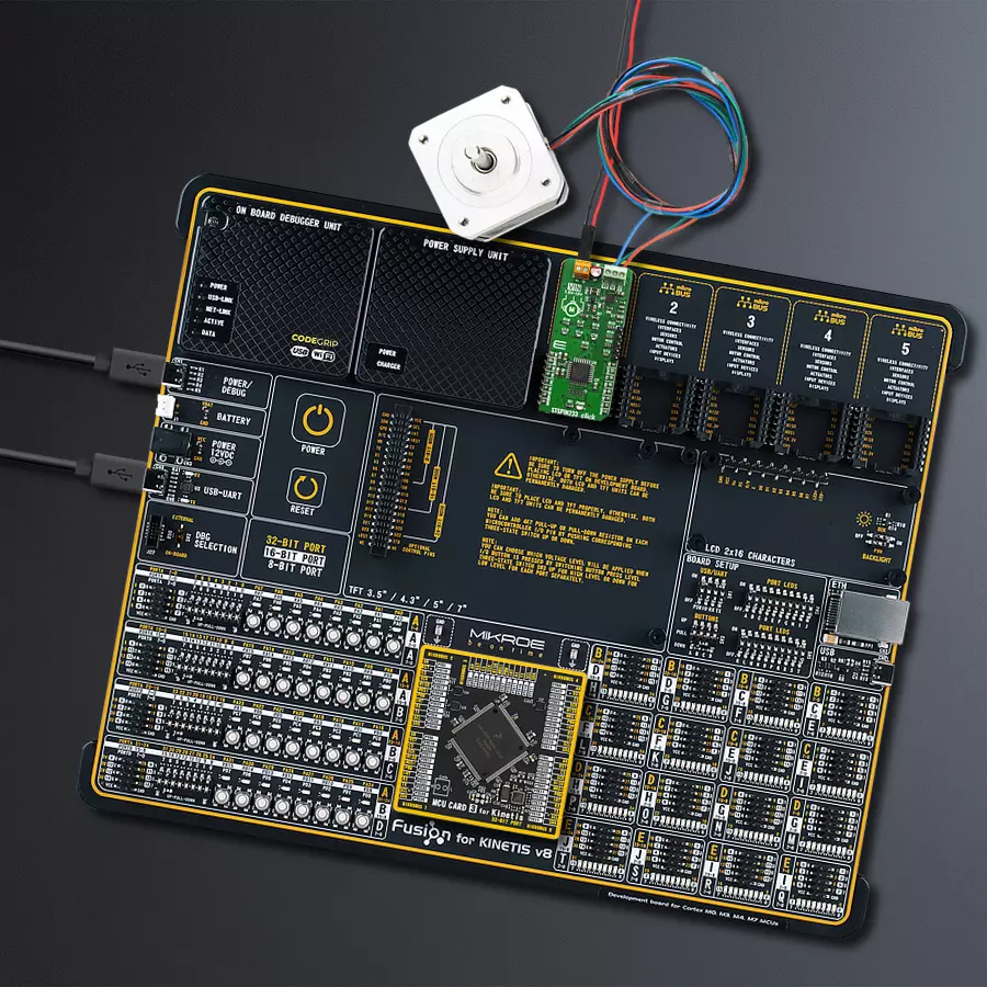
Fusion for KINETIS v8 is a development board specially designed for the needs of rapid development of embedded applications. It supports a wide range of microcontrollers, such as different 32-bit ARM® Cortex®-M based MCUs from NXP Semiconductor, regardless of their number of pins, and a broad set of unique functions, such as the first-ever embedded debugger/programmer over a WiFi network. The development board is well organized and designed so that the end-user has all the necessary elements, such as switches, buttons, indicators, connectors, and others, in one place. Thanks to innovative manufacturing technology, Fusion for KINETIS v8 provides a fluid and immersive working experience, allowing
access anywhere and under any circumstances at any time. Each part of the Fusion for KINETIS v8 development board contains the components necessary for the most efficient operation of the same board. An advanced integrated CODEGRIP programmer/debugger module offers many valuable programming/debugging options, including support for JTAG, SWD, and SWO Trace (Single Wire Output)), and seamless integration with the Mikroe software environment. Besides, it also includes a clean and regulated power supply module for the development board. It can use a wide range of external power sources, including a battery, an external 12V power supply, and a power source via the USB Type-C (USB-C) connector.
Communication options such as USB-UART, USB HOST/DEVICE, CAN (on the MCU card, if supported), and Ethernet is also included. In addition, it also has the well-established mikroBUS™ standard, a standardized socket for the MCU card (SiBRAIN standard), and two display options for the TFT board line of products and character-based LCD. Fusion for KINETIS v8 is an integral part of the Mikroe ecosystem for rapid development. Natively supported by Mikroe software tools, it covers many aspects of prototyping and development thanks to a considerable number of different Click boards™ (over a thousand boards), the number of which is growing every day.

Microcontroller Overview
MCU Card / MCU
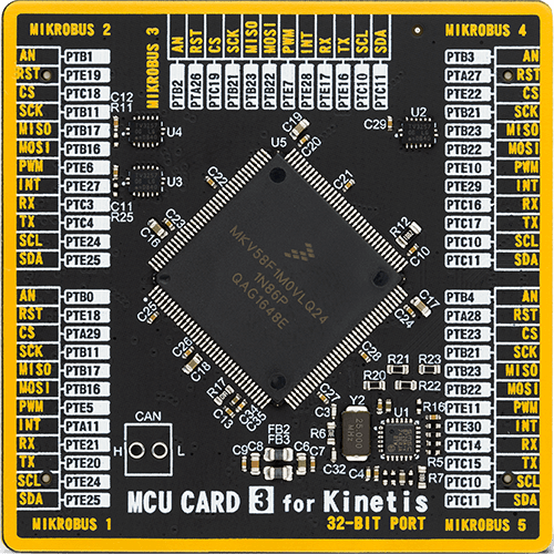
Type
8th Generation
Architecture
ARM Cortex-M7
MCU Memory (KB)
1024
Silicon Vendor
NXP
Pin count
144
RAM (Bytes)
262144
You complete me!
Accessories
Brushless DC (BLDC) Motor with a Hall sensor represents a high-performance motor from the 42BLF motor series. This motor, wired in a star configuration, boasts a Hall Effect angle of 120°, ensuring precise and reliable performance. With a compact motor length of 47mm and a lightweight design tipping the scales at just 0.29kg, this BLDC motor is engineered to meet your needs. Operating flawlessly at a voltage rating of 24VDC and a speed range of 4000 ± 10% RPM, this motor offers consistent and dependable power. It excels in a normal operational temperature range from -20 to +50°C, maintaining efficiency with a rated current of 1.9A. Also, this product seamlessly integrates with all Brushless Click boards™ and those that require BLDC motors with Hall sensors.

Used MCU Pins
mikroBUS™ mapper
Take a closer look
Click board™ Schematic

Step by step
Project assembly

Start by selecting your development board and Click board™. Begin with the Fusion for Kinetis v8 as your development board.


Track your results in real time
Application Output
1. Application Output - In Debug mode, the 'Application Output' window enables real-time data monitoring, offering direct insight into execution results. Ensure proper data display by configuring the environment correctly using the provided tutorial.

2. UART Terminal - Use the UART Terminal to monitor data transmission via a USB to UART converter, allowing direct communication between the Click board™ and your development system. Configure the baud rate and other serial settings according to your project's requirements to ensure proper functionality. For step-by-step setup instructions, refer to the provided tutorial.

3. Plot Output - The Plot feature offers a powerful way to visualize real-time sensor data, enabling trend analysis, debugging, and comparison of multiple data points. To set it up correctly, follow the provided tutorial, which includes a step-by-step example of using the Plot feature to display Click board™ readings. To use the Plot feature in your code, use the function: plot(*insert_graph_name*, variable_name);. This is a general format, and it is up to the user to replace 'insert_graph_name' with the actual graph name and 'variable_name' with the parameter to be displayed.

Software Support
Library Description
This library contains API for STPSIN233 Click driver.
Key functions:
stspin233_send_single_cmd- Send single commandstspin233_send_double_cmd- Send double commandstspin233_get_int_state- Get INT pin state
Open Source
Code example
The complete application code and a ready-to-use project are available through the NECTO Studio Package Manager for direct installation in the NECTO Studio. The application code can also be found on the MIKROE GitHub account.
/*!
* \file
* \brief Stspin233 Click example
*
* # Description
* This application is motor driver.
*
* The demo application is composed of two sections :
*
* ## Application Init
* Initializes driver and configures the Click board.
*
* ## Application Task
* This example demonstrates the use of STSPIN233 Click board, by running the motor clockwise and counter clockwise.
* All results will be displayed on USB UART.
*
* *note:*
* For all other commands that you can use to control your engine,
* see the firmware documentation. We used an 8 pole motor for the test.
*
* \author MikroE Team
*
*/
// ------------------------------------------------------------------- INCLUDES
#include "board.h"
#include "log.h"
#include "stspin233.h"
#include "string.h"
#define PROCESS_COUNTER 10
#define PROCESS_RX_BUFFER_SIZE 500
#define PROCESS_PARSER_BUFFER_SIZE 500
// ------------------------------------------------------------------ VARIABLES
static stspin233_t stspin233;
static log_t logger;
static char current_parser_buf[ PROCESS_PARSER_BUFFER_SIZE ];
// ------------------------------------------------------- ADDITIONAL FUNCTIONS
static void stspin233_process ( void )
{
int32_t rsp_size;
uint16_t rsp_cnt = 0;
char uart_rx_buffer[ PROCESS_RX_BUFFER_SIZE ] = { 0 };
uint16_t check_buf_cnt;
uint8_t process_cnt = PROCESS_COUNTER;
// Clear parser buffer
memset( current_parser_buf, 0 , PROCESS_PARSER_BUFFER_SIZE );
while( process_cnt != 0 )
{
rsp_size = stspin233_generic_read( &stspin233, &uart_rx_buffer, PROCESS_RX_BUFFER_SIZE );
if ( rsp_size > 0 )
{
// Validation of the received data
for ( check_buf_cnt = 0; check_buf_cnt < rsp_size; check_buf_cnt++ )
{
if ( uart_rx_buffer[ check_buf_cnt ] == 0 )
{
uart_rx_buffer[ check_buf_cnt ] = 13;
}
}
// Storages data in parser buffer
rsp_cnt += rsp_size;
if ( rsp_cnt < PROCESS_PARSER_BUFFER_SIZE )
{
strncat( current_parser_buf, uart_rx_buffer, rsp_size );
}
// Clear RX buffer
memset( uart_rx_buffer, 0, PROCESS_RX_BUFFER_SIZE );
}
else
{
process_cnt--;
// Process delay
Delay_100ms( );
}
}
}
// ------------------------------------------------------ APPLICATION FUNCTIONS
void application_init ( void )
{
log_cfg_t log_cfg;
stspin233_cfg_t cfg;
/**
* Logger initialization.
* Default baud rate: 115200
* Default log level: LOG_LEVEL_DEBUG
* @note If USB_UART_RX and USB_UART_TX
* are defined as HAL_PIN_NC, you will
* need to define them manually for log to work.
* See @b LOG_MAP_USB_UART macro definition for detailed explanation.
*/
LOG_MAP_USB_UART( log_cfg );
log_init( &logger, &log_cfg );
log_info( &logger, "---- Application Init ----" );
// Click initialization.
stspin233_cfg_setup( &cfg );
STSPIN233_MAP_MIKROBUS( cfg, MIKROBUS_1 );
stspin233_init( &stspin233, &cfg );
stspin233_default_cfg( &stspin233 );
}
void application_task ( void )
{
log_printf( &logger, ">>> START MOTOR\r\n" );
stspin233_send_single_cmd( &stspin233, STSPIN233_CMD_START_MOTOR );
stspin233_process( );
Delay_ms ( 1000 );
Delay_ms ( 1000 );
log_printf( &logger, ">>> Set clockwise direction\r\n" );
stspin233_send_double_cmd( &stspin233, STSPIN233_CMD_DIR_MOTOR, STSPIN233_CW_DIR );
stspin233_process( );
Delay_ms ( 1000 );
Delay_ms ( 1000 );
log_printf( &logger, ">>> Set counter clockwise direction\r\n" );
stspin233_send_double_cmd( &stspin233, STSPIN233_CMD_DIR_MOTOR, STSPIN233_CCW_DIR );
stspin233_process( );
Delay_ms ( 1000 );
Delay_ms ( 1000 );
log_printf( &logger, ">>> STOP MOTOR\r\n" );
stspin233_send_single_cmd( &stspin233, STSPIN233_CMD_STOP_MOTOR );
stspin233_process( );
Delay_ms ( 1000 );
Delay_ms ( 1000 );
stspin233_send_single_cmd( &stspin233, STSPIN233_CMD_STATUS );
stspin233_process( );
log_printf( &logger, ">>> STATUS: %.5s\r\n", ¤t_parser_buf[ 9 ] );
Delay_ms ( 1000 );
Delay_ms ( 1000 );
log_printf( &logger, "------------------------------\r\n" );
}
int main ( void )
{
/* Do not remove this line or clock might not be set correctly. */
#ifdef PREINIT_SUPPORTED
preinit();
#endif
application_init( );
for ( ; ; )
{
application_task( );
}
return 0;
}
// ------------------------------------------------------------------------ END