Achieve high-precision navigation and tracking capabilities, particularly in the automotive sector, with TESEO-VIC3DA and TM4C129ENCZAD
Upgrade automotive and precision applications with next-generation navigation and tracking technology
Published Feb 23, 2024
Click board™
GNSS 15 Click
Dev. board
Fusion for Tiva v8
Compiler
NECTO Studio
MCU
TM4C129ENCZAD
Precision GNSS tracking and accurate odometer readings converge in a single solution optimized for superior automotive navigation and distance monitoring
A
A
Hardware Overview
How does it work?
GNSS 15 Click is based on the TESEO-VIC3DA, an advanced automotive GNSS dead-reckoning module from STMicroelectronics that integrates a 6-axis IMU. This module stands out for its capability to simultaneously utilize data from multiple satellite constellations such as GPS, Galileo, Glonass, BeiDou, and QZSS, thanks to the TeseoIII single-die standalone positioning receiver IC. Additionally, it incorporates an ST 3D IMU sensor to facilitate Teseo dead reckoning in an automotive context (Teseo-DRAW). Thanks to its rich features, this Click board™ is designed for ease of use in automotive applications, delivering high accuracy, quick time-to-first-fix (TTFF), and reliable dead reckoning. The TESEO-VIC3DA supports firmware configurability and upgrades, further simplifying its integration and use. It features onboard firmware that eliminates the need for external memory for GNSS operations, including tracking, sensor fusion, and navigation. It enhances its usability with
features like autonomous assisted GNSS for up to 7 days and predictive and real-time assisted GNSS. GNSS 15 Click supports UART and I2C interfaces to communicate with a host MCU. By default, the board communicates via UART, providing various functionalities similar to the industry-standard 16C650 UART. When operating in I2C mode, the module functions as a slave device only. Besides communication pins, additional used pins on the mikroBUS™ socket include the WUP pin for asynchronous wake-up from Standby mode, the IRQ pin for internal event notifications, and the RST pin for module resets. The Click board™ features two specialized pins, FWD and WTICK, to acquire odometer information. The FWD pin indicates movement direction, with high and low logic levels signifying forward and backward movement, respectively. Meanwhile, the WTICK pin generates a pulse signal corresponding to wheel movement. An orange PPS LED indicator on the board
signifies the time pulse per second, which can be configured to various pulse conditions. Moreover, the GNSS 15 Click includes an SMA antenna connector for connecting an active GNSS antenna, available through the MIKROE shop. The antenna's circuit also utilizes a TPS22943 current-limited load switch from Texas Instruments to manage power consumption efficiently during Standby mode, optimizing for low-power operation. The TESEO-VIC3DA operates at a 3.3V logic voltage level, supplied through the mikroBUS™ power rail. It also has a backup supply, selected through a VBAT switch, provided via VEXT pins or a 3.3V power rail, ensuring compatibility with different power sources. When pairing the board with MCUs operating at non-3.3V logic levels, appropriate logic voltage level conversion is required. Additionally, this Click board™ comes equipped with a library containing functions and an example code that can be used as a reference for further development.

Features overview
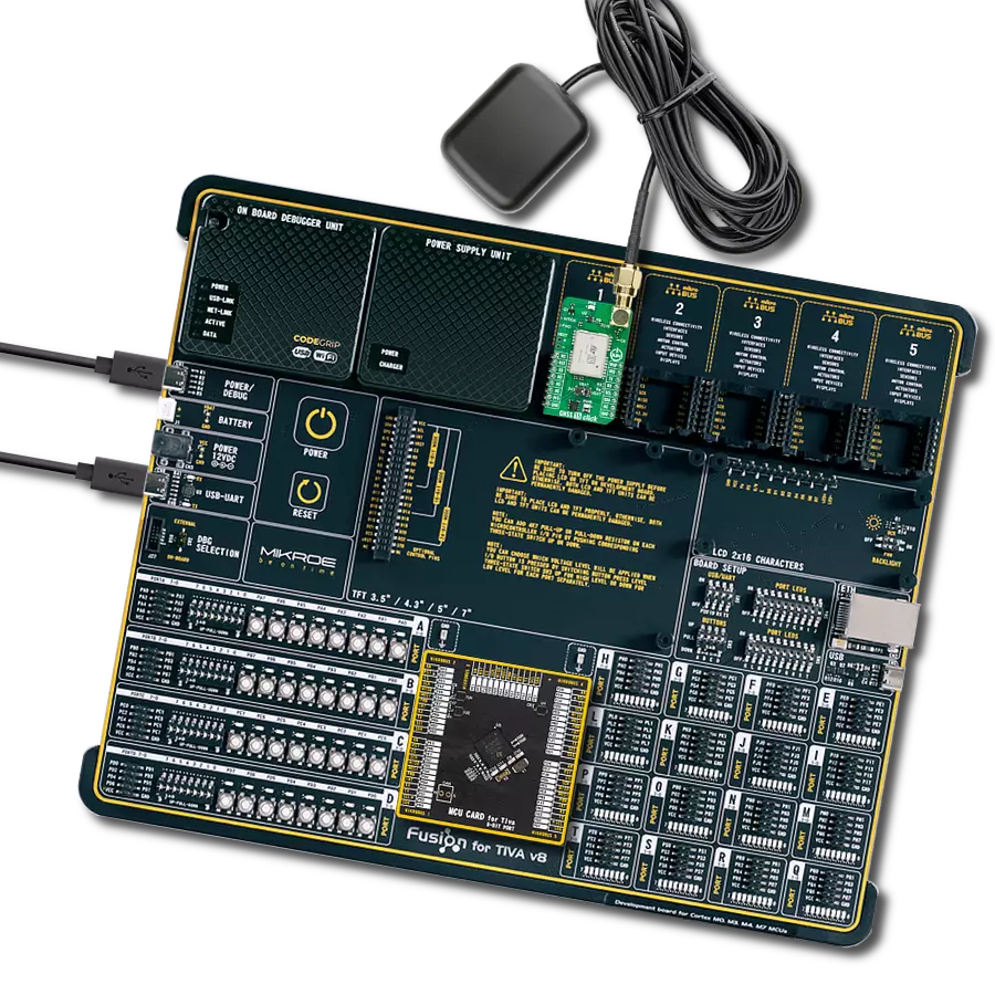
Development board
Fusion for TIVA v8 is a development board specially designed for the needs of rapid development of embedded applications. It supports a wide range of microcontrollers, such as different 32-bit ARM® Cortex®-M based MCUs from Texas Instruments, regardless of their number of pins, and a broad set of unique functions, such as the first-ever embedded debugger/programmer over a WiFi network. The development board is well organized and designed so that the end-user has all the necessary elements, such as switches, buttons, indicators, connectors, and others, in one place. Thanks to innovative manufacturing technology, Fusion for TIVA v8 provides a fluid and immersive working experience, allowing access
anywhere and under any circumstances at any time. Each part of the Fusion for TIVA v8 development board contains the components necessary for the most efficient operation of the same board. An advanced integrated CODEGRIP programmer/debugger module offers many valuable programming/debugging options, including support for JTAG, SWD, and SWO Trace (Single Wire Output)), and seamless integration with the Mikroe software environment. Besides, it also includes a clean and regulated power supply module for the development board. It can use a wide range of external power sources, including a battery, an external 12V power supply, and a power source via the USB Type-C (USB-C) connector.
Communication options such as USB-UART, USB HOST/DEVICE, CAN (on the MCU card, if supported), and Ethernet is also included. In addition, it also has the well-established mikroBUS™ standard, a standardized socket for the MCU card (SiBRAIN standard), and two display options for the TFT board line of products and character-based LCD. Fusion for TIVA v8 is an integral part of the Mikroe ecosystem for rapid development. Natively supported by Mikroe software tools, it covers many aspects of prototyping and development thanks to a considerable number of different Click boards™ (over a thousand boards), the number of which is growing every day.

Microcontroller Overview
MCU Card / MCU
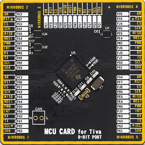
Type
8th Generation
Architecture
ARM Cortex-M4
MCU Memory (KB)
1024
Silicon Vendor
Texas Instruments
Pin count
212
RAM (Bytes)
262144
You complete me!
Accessories
Active GPS antenna is designed to enhance the performance of your GPS and GNSS Click boards™. This external antenna boasts a robust construction, making it ideal for various weather conditions. With a frequency range of 1575.42MHz and a 50Ohm impedance, it ensures reliable signal reception. The antenna delivers a gain of greater than -4dBic within a wide angular range, securing over 75% coverage. The bandwidth of +/- 5MHz further guarantees precise data acquisition. Featuring a Right-Hand Circular Polarization (RHCP), this antenna offers stable signal reception. Its compact dimensions of 48.53915mm and a 2-meter cable make it easy to install. The magnetic antenna type with an SMA male connector ensures a secure and convenient connection. If you require a dependable external antenna for your locator device, our active GPS antenna is the perfect solution.

Used MCU Pins
mikroBUS™ mapper
Take a closer look
Click board™ Schematic

Step by step
Project assembly

Start by selecting your development board and Click board™. Begin with the Fusion for Tiva v8 as your development board.


Software Support
Library Description
This library contains API for GNSS 15 Click driver.
Key functions:
gnss15_parse_gpgga- This function parses the GPGGA data from the read response buffergnss15_reset_device- This function resets the device by toggling the RST pin
Open Source
Code example
The complete application code and a ready-to-use project are available through the NECTO Studio Package Manager for direct installation in the NECTO Studio. The application code can also be found on the MIKROE GitHub account.
/*!
 * @file main.c
 * @brief GNSS 15 Click Example.
 *
 * # Description
 * This example demonstrates the use of GNSS 15 Click board by processing
 * the incoming data and displaying them on the USB UART.
 *
 * The demo application is composed of two sections :
 *
 * ## Application Init
 * Initializes the driver and resets the Click board.
 *
 * ## Application Task
 * Reads the received data, parses the GPGGA info from it, and once it receives the position fix
 * it will start displaying the coordinates on the USB UART.
 *
 * ## Additional Function
 * - static void gnss15_clear_app_buf ( void )
 * - static err_t gnss15_process ( gnss15_t *ctx )
 * - static void gnss15_parser_application ( uint8_t *rsp )
 *
 * @author Nenad Filipovic
 *
 */

#include "board.h"
#include "log.h"
#include "gnss15.h"

// Application buffer size
#define PROCESS_BUFFER_SIZE         200

static gnss15_t gnss15;
static log_t logger;

static uint8_t app_buf[ PROCESS_BUFFER_SIZE ] = { 0 };
static int32_t app_buf_len = 0;

/**
 * @brief GNSS 15 clearing application buffer.
 * @details This function clears memory of application buffer and reset its length.
 * @note None.
 */
static void gnss15_clear_app_buf ( void );

/**
 * @brief GNSS 15 data reading function.
 * @details This function reads data from device and concatenates data to application buffer.
 * @param[in] ctx : Click context object.
 * See #gnss15_t object definition for detailed explanation.
 * @return @li @c  0 - Read some data.
 *         @li @c -1 - Nothing is read.
 * See #err_t definition for detailed explanation.
 * @note None.
 */
static err_t gnss15_process ( gnss15_t *ctx );

/**
 * @brief GNSS 15 parser application.
 * @details This function reads and parse data from device.
 * @param[in] rsp Response buffer.
 * @details This function logs GNSS data on the USB UART.
 * @return None.
 * @note None.
 */
static void gnss15_parser_application ( uint8_t *rsp );

void application_init ( void )
{
    log_cfg_t log_cfg;  /**< Logger config object. */
    gnss15_cfg_t gnss15_cfg;  /**< Click config object. */

    /**
     * Logger initialization.
     * Default baud rate: 115200
     * Default log level: LOG_LEVEL_DEBUG
     * @note If USB_UART_RX and USB_UART_TX
     * are defined as HAL_PIN_NC, you will
     * need to define them manually for log to work.
     * See @b LOG_MAP_USB_UART macro definition for detailed explanation.
     */
    LOG_MAP_USB_UART( log_cfg );
    log_init( &logger, &log_cfg );
    log_info( &logger, " Application Init " );

    // Click initialization.
    gnss15_cfg_setup( &gnss15_cfg );
    GNSS15_MAP_MIKROBUS( gnss15_cfg, MIKROBUS_1 );
    if ( UART_ERROR == gnss15_init( &gnss15, &gnss15_cfg ) )
    {
        log_error( &logger, " Communication init." );
        for ( ; ; );
    }

    log_info( &logger, " Application Task " );
}

void application_task ( void )
{
    if ( GNSS15_OK == gnss15_process( &gnss15 ) )
    {
        if ( app_buf_len > ( sizeof ( GNSS15_RSP_GPGGA ) + GNSS15_GPGGA_ELEMENT_SIZE ) )
        {
            gnss15_parser_application( app_buf );
        }
    }
}

int main ( void )
{
    /* Do not remove this line or clock might not be set correctly. */
    #ifdef PREINIT_SUPPORTED
    preinit();
    #endif

    application_init( );

    for ( ; ; )
    {
        application_task( );
    }

    return 0;
}

static void gnss15_clear_app_buf ( void )
{
    memset( app_buf, 0, app_buf_len );
    app_buf_len = 0;
}

static err_t gnss15_process ( gnss15_t *ctx )
{
    int32_t rx_size = 0;
    uint8_t rx_buf[ PROCESS_BUFFER_SIZE ] = { 0 };
    if ( GNSS15_DRV_SEL_UART == ctx->drv_sel )
    {
        rx_size = gnss15_generic_read( ctx, rx_buf, PROCESS_BUFFER_SIZE );
    }
    else
    {
        if ( GNSS15_OK == gnss15_generic_read( ctx, rx_buf, 1 ) )
        {
            if ( GNSS15_DUMMY != rx_buf[ 0 ] )
            {
                rx_size = 1;
            }
        }
    }
    if ( rx_size > 0 )
    {
        int32_t buf_cnt = app_buf_len;
        if ( ( ( app_buf_len + rx_size ) > PROCESS_BUFFER_SIZE ) && ( app_buf_len > 0 ) )
        {
            buf_cnt = PROCESS_BUFFER_SIZE - ( ( app_buf_len + rx_size ) - PROCESS_BUFFER_SIZE );
            memmove ( app_buf, &app_buf[ PROCESS_BUFFER_SIZE - buf_cnt ], buf_cnt );
        }
        for ( int32_t rx_cnt = 0; rx_cnt < rx_size; rx_cnt++ )
        {
            if ( rx_buf[ rx_cnt ] )
            {
                app_buf[ buf_cnt++ ] = rx_buf[ rx_cnt ];
                if ( app_buf_len < PROCESS_BUFFER_SIZE )
                {
                    app_buf_len++;
                }
            }
        }
        return GNSS15_OK;
    }
    return GNSS15_ERROR;
}

static void gnss15_parser_application ( uint8_t *rsp )
{
    uint8_t element_buf[ 100 ] = { 0 };
    if ( GNSS15_OK == gnss15_parse_gpgga( rsp, GNSS15_GPGGA_LATITUDE, element_buf ) )
    {
        static uint8_t wait_for_fix_cnt = 0;
        if ( ( strlen( element_buf ) > 0 ) && ( !strstr ( element_buf, GNSS15_RSP_NO_FIX ) ) )
        {
            log_printf( &logger, "\r\n Latitude: %.2s degrees, %s minutes \r\n", element_buf, &element_buf[ 2 ] );
            gnss15_parse_gpgga( rsp, GNSS15_GPGGA_LONGITUDE, element_buf );
            log_printf( &logger, " Longitude: %.3s degrees, %s minutes \r\n", element_buf, &element_buf[ 3 ] );
            memset( element_buf, 0, sizeof( element_buf ) );
            gnss15_parse_gpgga( rsp, GNSS15_GPGGA_ALTITUDE, element_buf );
            log_printf( &logger, " Altitude: %s m \r\n", element_buf );
            wait_for_fix_cnt = 0;
        }
        else
        {
            if ( wait_for_fix_cnt % 5 == 0 )
            {
                log_printf( &logger, " Waiting for the position fix...\r\n\n" );
                wait_for_fix_cnt = 0;
            }
            wait_for_fix_cnt++;
        }
        gnss15_clear_app_buf(  );
    }
}

// ------------------------------------------------------------------------ END
Additional Support
Resources
Category:GPS/GNSS


