Unlock a new era of efficient data transmission with TFBS4650 and TM4C123GH6PZ
Swift data transfer in infrared waves!

Published Nov 11, 2023
Click board™
IrDA 4 Click
Dev Board
Fusion for ARM v8
Compiler
NECTO Studio
MCU
TM4C123GH6PZ
Experience the magic of infrared technology as our transceiver facilitates seamless data exchange, making connectivity effortless and efficient.
A
A
Hardware Overview
How does it work?
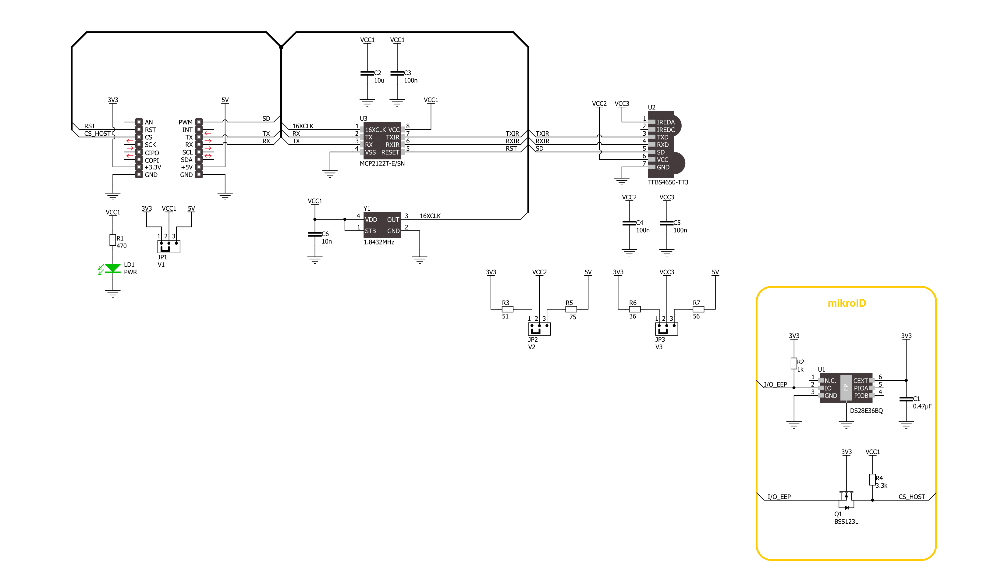
IrDA 4 Click is based on the TFBS4650, an infrared transceiver from Vishay Semiconductors. It is a low-power consumption device with a standard IrDA link distance of 1m. At this distance, the transceiver supports data rates up to 115kbit/s per the IrDA standard. The MCP2120 encodes an asynchronous serial data stream, converting each data bit to the corresponding Infrared (IR) formatted pulse, with received IR pulses decoded back into the corresponding UART formatted serial data. The combination of the MCP2120 and TFBS4650 results in fast and stable infrared data communication covering the full IrDA range in
distance and speed. To communicate with the host MCU, IrDA 4 Click uses MCP2120 and its onboard clock generator for the fastest possible UART performance of 115.200 bps, so it does not need an additional clock signal to be generated by the MCU. The RST pin of the mikroBUS™ socket can reset the MCP2120, while the SD pin with an active HIGH logic state can be used to put the TFBS4650 into a Shutdown state. This Click board™ can operate with either 3.3V or 5V logic voltage levels selected via the VCC SEL V1 jumper. This way, both 3.3V and 5V capable MCUs can use the communication lines properly. Apart from
the V1 jumper, there are two more: V2 and V3. The V2 jumper serves as the main power supply of the TFBS4650, while the V3 jumper allows you to set the voltage specifically for its IRED anode. Each of these positions can be selected independently, allowing you the flexibility to choose the configuration that best suits your requirements. Also, this Click board™ comes equipped with a library containing easy-to-use functions and an example code that can be used as a reference for further development.

Features overview
Development board
Fusion for ARM v8 is a development board specially designed for the needs of rapid development of embedded applications. It supports a wide range of microcontrollers, such as different ARM® Cortex®-M based MCUs regardless of their number of pins, and a broad set of unique functions, such as the first-ever embedded debugger/programmer over WiFi. The development board is well organized and designed so that the end-user has all the necessary elements, such as switches, buttons, indicators, connectors, and others, in one place. Thanks to innovative manufacturing technology, Fusion for ARM v8 provides a fluid and immersive working experience, allowing access anywhere and under any
circumstances at any time. Each part of the Fusion for ARM v8 development board contains the components necessary for the most efficient operation of the same board. An advanced integrated CODEGRIP programmer/debugger module offers many valuable programming/debugging options, including support for JTAG, SWD, and SWO Trace (Single Wire Output)), and seamless integration with the Mikroe software environment. Besides, it also includes a clean and regulated power supply module for the development board. It can use a wide range of external power sources, including a battery, an external 12V power supply, and a power source via the USB Type-C (USB-C) connector.
Communication options such as USB-UART, USB HOST/DEVICE, CAN (on the MCU card, if supported), and Ethernet is also included. In addition, it also has the well-established mikroBUS™ standard, a standardized socket for the MCU card (SiBRAIN standard), and two display options for the TFT board line of products and character-based LCD. Fusion for ARM v8 is an integral part of the Mikroe ecosystem for rapid development. Natively supported by Mikroe software tools, it covers many aspects of prototyping and development thanks to a considerable number of different Click boards™ (over a thousand boards), the number of which is growing every day.

Microcontroller Overview
MCU Card / MCU
Type
8th Generation
Architecture
ARM Cortex-M4
MCU Memory (KB)
256
Silicon Vendor
Texas Instruments
Pin count
100
RAM (Bytes)
32768
Used MCU Pins
mikroBUS™ mapper
Take a closer look
Schematic
Step by step
Project assembly

Start by selecting your development board and Click board™. Begin with the Fusion for ARM v8 as your development board.


Track your results in real time
Application Output
After pressing the "FLASH" button on the left-side panel, it is necessary to open the UART terminal to display the achieved results. By clicking on the Tools icon in the right-hand panel, multiple different functions are displayed, among which is the UART Terminal. Click on the offered "UART Terminal" icon.

Once the UART terminal is opened, the window takes on a new form. At the top of the tab are two buttons, one for adjusting the parameters of the UART terminal and the other for connecting the UART terminal. The tab's lower part is reserved for displaying the achieved results. Before connecting, the terminal has a Disconnected status, indicating that the terminal is not yet active. Before connecting, it is necessary to check the set parameters of the UART terminal. Click on the "OPTIONS" button.

In the newly opened UART Terminal Options field, we check if the terminal settings are correct, such as the set port and the Baud rate of UART communication. If the data is not displayed properly, it is possible that the Baud rate value is not set correctly and needs to be adjusted to 115200. If all the parameters are set correctly, click on "CONFIGURE".

The next step is to click on the "CONNECT" button, after which the terminal status changes from Disconnected to Connected in green, and the data is displayed in the Received data field.

Software Support
Library Description
This library contains API for IrDA 4 Click driver.
Key functions:
irda4_generic_write- IrDA 4 data writing function.irda4_generic_read- IrDA 4 data reading function.irda_hw_reset- IrDA 4 hardware reset function.
Open Source
Code example
This example can be found in NECTO Studio. Feel free to download the code, or you can copy the code below.
/*!
 * @file main.c
 * @brief IrDA 4 Click Example.
 *
 * # Description
 * This example demonstrates the use of IrDA 4 click board by processing
 * the incoming data and displaying them on the USB UART.
 *
 * The demo application is composed of two sections :
 *
 * ## Application Init
 * Initializes the driver and disables the transmitter shutdown.
 *
 * ## Application Task
 * Demonstrates the use of IrDA 4 clicks which can be used as transmitter or receiver.
 * - TRANSMITTER : Device is sending tx_message data.
 * - RECEIVER    : Device is reading a message that is being transmitted and
 *                 logs it on the UART terminal.
 *
 * @author Stefan Ilic
 *
 */

#include "board.h"
#include "log.h"
#include "irda4.h"

// To configure the driver into receiver mode comment out the line below.
#define DEMO_APP_TRANSMITTER

static irda4_t irda4;
static log_t logger;

static uint8_t tx_message[ 8 ] = { 'M', 'i', 'k', 'r', 'o', 'E', '\r', '\n' };
static uint8_t rx_message;

void application_init ( void )
{
    log_cfg_t log_cfg;  /**< Logger config object. */
    irda4_cfg_t irda4_cfg;  /**< Click config object. */

    /**
     * Logger initialization.
     * Default baud rate: 115200
     * Default log level: LOG_LEVEL_DEBUG
     * @note If USB_UART_RX and USB_UART_TX
     * are defined as HAL_PIN_NC, you will
     * need to define them manually for log to work.
     * See @b LOG_MAP_USB_UART macro definition for detailed explanation.
     */
    LOG_MAP_USB_UART( log_cfg );
    log_init( &logger, &log_cfg );
    log_info( &logger, " Application Init " );

    // Click initialization.
    irda4_cfg_setup( &irda4_cfg );
    IRDA4_MAP_MIKROBUS( irda4_cfg, MIKROBUS_1 );
    if ( UART_ERROR == irda4_init( &irda4, &irda4_cfg ) )
    {
        log_error( &logger, " Communication init." );
        for ( ; ; );
    }

    irda4_set_tx_shutdown( &irda4, IRDA4_SHUTDOWN_DISABLED );

    log_info( &logger, " Application Task " );
}

void application_task ( void )
{
#if defined( DEMO_APP_TRANSMITTER )
    for ( uint8_t n_cnt = 0; n_cnt < 8; n_cnt++ )
    {
        irda4_generic_write( &irda4, &tx_message[ n_cnt ], 1 );
        Delay_ms( 500 );
    }
    log_printf( &logger, "Message sent \r\n" );
#else
    if ( 1 == irda4_generic_read( &irda4, &rx_message, 1 ) )
    {
        log_printf( &logger, "%c", rx_message );
    }
#endif
}

void main ( void )
{
    application_init( );

    for ( ; ; )
    {
        application_task( );
    }
}

// ------------------------------------------------------------------------ END


