Illuminate, animate, and inspire with WS2812 and TM4C123GH6PZ
Pixels awaken!

Published Sep 05, 2023
Click board™
10x10 RGB Click
Dev. board
Fusion for Tiva v8
Compiler
NECTO Studio
MCU
TM4C123GH6PZ
Our solution, featuring a 10x10 display matrix of 100 'intelligent' RGB elements, transforms your creative ideas into mesmerizing visuals, making it the ultimate choice for dynamic displays, animations, and interactive presentations
A
A
Hardware Overview
How does it work?
10x10 RGB Click is based on the WS2812, an intelligent control LED light source from Worldsemi. Its exterior adopts the latest MOLDING packaging technology, and the control circuit and RGB chips are integrated into a package of 2020 components. It's internal includes an intelligent digital port data latch and signal reshaping amplification drive circuit. It also includes a precision internal oscillator and a voltage-programmable constant current control part, ensuring consistent pixel point light color height. The data transfer protocol use single NZR communication mode. After the pixel power-on reset, the DIN port receive data from controller, the first pixel collect initial 24bit data then sent to the internal data latch, the other data which reshaping by the internal signal reshaping amplification circuit sent to the next cascade pixel through the DO port. After transmission for each
pixel, the signal to reduce 24bit. pixel adopt auto reshaping transmit technology, making the pixel cascade number is not limited the signal transmission, only depend on the speed of signal transmission. RESET time >280μs , it won't cause wrong reset while interruption, it supports the lower frequency and inexpensive MCU. Refresh Frequency updates to 2KHz, Low Frame Frequency and No Flicker appear in HD Video Camera, it improve excellent display effect. LED with low driving voltage, environmental protection and energy saving, high brightness, large scattering angle, good consistency, low power, long life and other advantages. The control chip integrated in LED above becoming more simple circuit, small volume, convenient installation. 10x10 RGB Click can be used in many applications, like full-color module, full color soft lights a lamp strip, LED decorative lighting, indoor/outdoor LED
irregular screen, game machine and amusement equipment, and more. The INT pin of the mikroBUS™, which is labeled as DO on this Click board™, allows cascading of multiple 10x10 RGB click devices. It simply routes the data line back to the mikroBUS™, allowing it to be re-used for the next 10x10 RGB click, and so on. The length of the whole chain is limited only by the communication speed, required to scan through all the LED devices, in order to maintain a reasonable refresh speed. This Click board™ can be operated only with a 3.3V logic voltage level. The board must perform appropriate logic voltage level conversion before using MCUs with different logic levels. Also, it comes equipped with a library containing functions and an example code that can be used as a reference for further development.


Features overview
Development board
Fusion for TIVA v8 is a development board specially designed for the needs of rapid development of embedded applications. It supports a wide range of microcontrollers, such as different 32-bit ARM® Cortex®-M based MCUs from Texas Instruments, regardless of their number of pins, and a broad set of unique functions, such as the first-ever embedded debugger/programmer over a WiFi network. The development board is well organized and designed so that the end-user has all the necessary elements, such as switches, buttons, indicators, connectors, and others, in one place. Thanks to innovative manufacturing technology, Fusion for TIVA v8 provides a fluid and immersive working experience, allowing access
anywhere and under any circumstances at any time. Each part of the Fusion for TIVA v8 development board contains the components necessary for the most efficient operation of the same board. An advanced integrated CODEGRIP programmer/debugger module offers many valuable programming/debugging options, including support for JTAG, SWD, and SWO Trace (Single Wire Output)), and seamless integration with the Mikroe software environment. Besides, it also includes a clean and regulated power supply module for the development board. It can use a wide range of external power sources, including a battery, an external 12V power supply, and a power source via the USB Type-C (USB-C) connector.
Communication options such as USB-UART, USB HOST/DEVICE, CAN (on the MCU card, if supported), and Ethernet is also included. In addition, it also has the well-established mikroBUS™ standard, a standardized socket for the MCU card (SiBRAIN standard), and two display options for the TFT board line of products and character-based LCD. Fusion for TIVA v8 is an integral part of the Mikroe ecosystem for rapid development. Natively supported by Mikroe software tools, it covers many aspects of prototyping and development thanks to a considerable number of different Click boards™ (over a thousand boards), the number of which is growing every day.

Microcontroller Overview
MCU Card / MCU
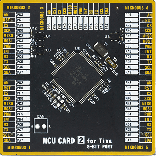
Type
8th Generation
Architecture
ARM Cortex-M4
MCU Memory (KB)
256
Silicon Vendor
Texas Instruments
Pin count
100
RAM (Bytes)
32768
Used MCU Pins
mikroBUS™ mapper
Take a closer look
Click board™ Schematic

Step by step
Project assembly

Start by selecting your development board and Click board™. Begin with the Fusion for Tiva v8 as your development board.


Software Support
Library Description
This library contains API for 10x10 RGB Click driver.
Key functions:
c10x10rgb_display_image- This function displays an image from the specified demo_image addressc10x10rgb_display_byte- This function displays the specified bytec10x10rgb_display_string- This function displays the specified string.
Open Source
Code example
The complete application code and a ready-to-use project are available through the NECTO Studio Package Manager for direct installation in the NECTO Studio. The application code can also be found on the MIKROE GitHub account.
/*!
 * \file
 * \brief 10x10 RGB Click example
 *
 * # Description
 * This example showcases how to initialize, configure and use the 10x10 RGB Click module. The
 * Click has a 10 by 10 RGB LED matrix which can be programmed to show different colors or even
 * images. LED elements that form the matrix communicate by a single line with the host MCU.
 *
 * The demo application is composed of two sections :
 *
 * ## Application Init
 * This function initializes and configures the Click board.
 *
 * ## Application Task
 * This function first displays 3 chars { R, G, B }, the string "MIKROE", the company logo and
 * a rainbow in the end.
 *
 * @note
 * Make sure the logic delays are defined for your system in the c10x10rgb_delays.h file.
 *
 * \author MikroE Team
 *
 */
// ------------------------------------------------------------------- INCLUDES

#include "board.h"
#include "c10x10rgb.h"
#include "c10x10rgb_delays.h"

// ------------------------------------------------------------------ VARIABLES

static c10x10rgb_t c10x10rgb;

const uint32_t MIKROE_IMAGE[ 100 ] =
{
    0x000000,0x000000,0x000000,0x000000,0x000000,0x000000,0x000000,0x000000,0x000000,0x000000,
    0x000000,0x000000,0x000000,0x000000,0x000000,0x000000,0x000000,0x000000,0x000000,0x000000,
    0x000000,0x000000,0x181800,0x181800,0x181800,0x181800,0x181800,0x181800,0x181800,0x000000,
    0x000000,0x181800,0x000000,0x000000,0x000000,0x000000,0x000000,0x000000,0x000000,0x000000,
    0x000000,0x181800,0x181800,0x181800,0x181800,0x181800,0x181800,0x181800,0x181800,0x000000,
    0x000000,0x181800,0x181800,0x181800,0x181800,0x181800,0x181800,0x181800,0x181800,0x000000,
    0x000000,0x181800,0x000000,0x000000,0x000000,0x000000,0x000000,0x000000,0x000000,0x000000,
    0x000000,0x000000,0x181800,0x181800,0x181800,0x181800,0x181800,0x181800,0x181800,0x000000,
    0x000000,0x000000,0x000000,0x000000,0x000000,0x000000,0x000000,0x000000,0x000000,0x000000,
    0x000000,0x000000,0x000000,0x000000,0x000000,0x000000,0x000000,0x000000,0x000000,0x000000
};

static c10x10rgb_byte_t scroll_data_obj[ 6 ] =
{
    { 'M', C10X10RGB_COLOR_OFF, C10X10RGB_COLOR_YELLOW_25, C10X10RGB_SCROLL_ROTATE_V },
    { 'I', C10X10RGB_COLOR_OFF, C10X10RGB_COLOR_YELLOW_25, C10X10RGB_SCROLL_ROTATE_V },
    { 'K', C10X10RGB_COLOR_OFF, C10X10RGB_COLOR_YELLOW_25, C10X10RGB_SCROLL_ROTATE_V },
    { 'R', C10X10RGB_COLOR_OFF, C10X10RGB_COLOR_YELLOW_25, C10X10RGB_SCROLL_ROTATE_V },
    { 'O', C10X10RGB_COLOR_OFF, C10X10RGB_COLOR_YELLOW_25, C10X10RGB_SCROLL_ROTATE_V },
    { 'E', C10X10RGB_COLOR_YELLOW_25, C10X10RGB_COLOR_OFF, C10X10RGB_SCROLL_ROTATE_V }
};

static uint16_t scroll_speed_ms = 100;
static uint8_t scroll_data_len = 6;

static c10x10rgb_byte_t rgb_data_byte[ 3 ] =
{
    { 'R', C10X10RGB_COLOR_RED_25, C10X10RGB_COLOR_OFF, C10X10RGB_BYTE_ROTATE_H_UP },
    { 'G', C10X10RGB_COLOR_OFF, C10X10RGB_COLOR_GREEN_25, C10X10RGB_BYTE_ROTATE_H_UP },
    { 'B', C10X10RGB_COLOR_BLUE_25, C10X10RGB_COLOR_OFF, C10X10RGB_BYTE_ROTATE_H_UP }
};

static uint8_t rainbow_brightness = 10;
static uint16_t rainbow_speed_ms = 20;

// ------------------------------------------------------- ADDITIONAL FUNCTIONS

static void logic_zero ( void )
{
    hal_ll_gpio_set_pin_output( &c10x10rgb.di_pin.pin );
    DELAY_TOH;
    hal_ll_gpio_clear_pin_output( &c10x10rgb.di_pin.pin );
    DELAY_TOL;
}

static void logic_one ( void )
{
    hal_ll_gpio_set_pin_output( &c10x10rgb.di_pin.pin );
    DELAY_T1H;
    hal_ll_gpio_clear_pin_output( &c10x10rgb.di_pin.pin );
    DELAY_T1L;
}

// ------------------------------------------------------ APPLICATION FUNCTIONS

void application_init ( void )
{
    c10x10rgb_cfg_t cfg;

    //  Click initialization.
    c10x10rgb_cfg_setup( &cfg, &logic_zero, &logic_one );
    C10X10RGB_MAP_MIKROBUS( cfg, MIKROBUS_1 );
    c10x10rgb_init( &c10x10rgb, &cfg );

    c10x10rgb_fill_screen( &c10x10rgb, C10X10RGB_COLOR_OFF );
    Delay_ms ( 1000 );
}

void application_task ( void )
{
    c10x10rgb_display_byte ( &c10x10rgb, &rgb_data_byte[ 0 ] );
    Delay_ms ( 1000 );
    c10x10rgb_display_byte ( &c10x10rgb, &rgb_data_byte[ 1 ] );
    Delay_ms ( 1000 );
    c10x10rgb_display_byte ( &c10x10rgb, &rgb_data_byte[ 2 ] );
    Delay_ms ( 1000 );
    Delay_ms ( 1000 );

    c10x10rgb_display_string( &c10x10rgb, &scroll_data_obj, scroll_data_len, scroll_speed_ms );
    Delay_ms ( 1000 );
    c10x10rgb_display_image( &c10x10rgb, &MIKROE_IMAGE[ 0 ] );
    Delay_ms ( 1000 );
    Delay_ms ( 1000 );
    Delay_ms ( 1000 );
    c10x10rgb_demo_rainbow( &c10x10rgb, rainbow_brightness, rainbow_speed_ms );
    Delay_ms ( 1000 );
}

int main ( void )
{
    /* Do not remove this line or clock might not be set correctly. */
    #ifdef PREINIT_SUPPORTED
    preinit();
    #endif

    application_init( );

    for ( ; ; )
    {
        application_task( );
    }

    return 0;
}

// ------------------------------------------------------------------------ END
Additional Support
Resources
Category:LED Matrix


