Elevate your projects to new heights with DRV8411A and PIC18F4458
Seamless control, infinite possibilities
Published Nov 01, 2023
Click board™
H-Bridge 13 Click
Dev. board
EasyPIC v7a
Compiler
NECTO Studio
MCU
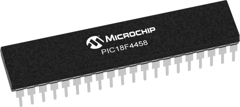
PIC18F4458
With its H-bridge design, our motor driver offers a robust and compact solution for powering and controlling DC motors, ensuring optimal performance in diverse electronic projects.
A
A
Hardware Overview
How does it work?
H-Bridge 13 Click is based on the DRV8411A, a dual H-Bridge motor driver with current regulations from Texas Instruments. The Tripler charge pump integrates all capacitors and allows for 100% duty cycle operation. The inputs and outputs can be paralleled to drive high-current brush DC motors. It also implements current sensing and regulation parts. Internal current mirrors output the current sense information on the IPROPI pins, eliminating the need for large power shunt resistors, thereby saving board area, reducing system cost, and allowing the host MCU to detect motor stalls or changes in load conditions. Four screw terminals connect the motors, and one VM external power supply is input to power the motors. The motor driver comes with several protection features, such as a VM undervoltage lockout (UVLO), auto-recovery overcurrent protection (OCP), thermal shutdown (TSD), and fault indication. The integrated current regulation feature limits motor current to a predefined maximum based on the VREF and xIPROPI settings. The xIPROPI signal can provide current feedback to a microcontroller
during the H-bridges drive and brake/slow-decay states. The reference voltage can be selected over the onboard 3.3V rail or an external one over the VREF SEL jumper, where the 3.3V is selected by default. The external reference voltage can be connected over the VREF EXT header. The H-Bridge control inputs for the motor driver's full bridges A and B are fed by two TS5A23157s, dual 10Ω SPDT analog switches from Texas Instruments. These single-pole double-throw switches are designed to handle both digital and analog signals. They feature a low-charge injection, excellent ON-resistance matching, and low total harmonic distortion. Normally closed IO ports of this switch are controlled over the PCA9538A, a low-voltage 8-bit IO port with interrupt and reset from NXP Semiconductors. The analog current output that is proportional to the load current for full bridges A and B can be monitored by selecting one of the channels at a time over the 74LVC1G3157GV.125, a 10Ω single-pole double-throw analog switch from Nexperia. H-Bridge 13 Clisk uses a standard 2-Wire I2C interface of the
PCA9538A to communicate with the host MCU, supporting fast mode up to 400KHz. The I2C address can be selected over the ADDR SEL jumper, where 0 is selected by default. By controlling the PCA9538A, you can control the switches, the PWM signal, full bridge inputs, and the motor driver itself. You can also read the DRV8411A's fault indicator over the I2C interface and the interrupt INT pin. The speed of the motors can be controlled over the PWM pin and the TS5A23157s switches. The analog current outputs can be read over the AN pin by selecting one of the bridges over the PCA9538A and I2C interface. The PCA9538A can be reset over the RST pin. This Click board™ can operate with either 3.3V or 5V logic voltage levels selected via the PWR SEL jumper. This way, both 3.3V and 5V capable MCUs can use the communication lines properly. Also, this Click board™ comes equipped with a library containing easy-to-use functions and an example code that can be used as a reference for further development.

Features overview
Development board
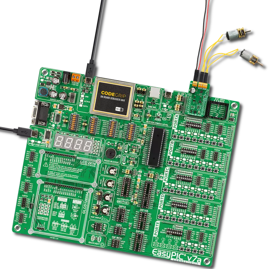
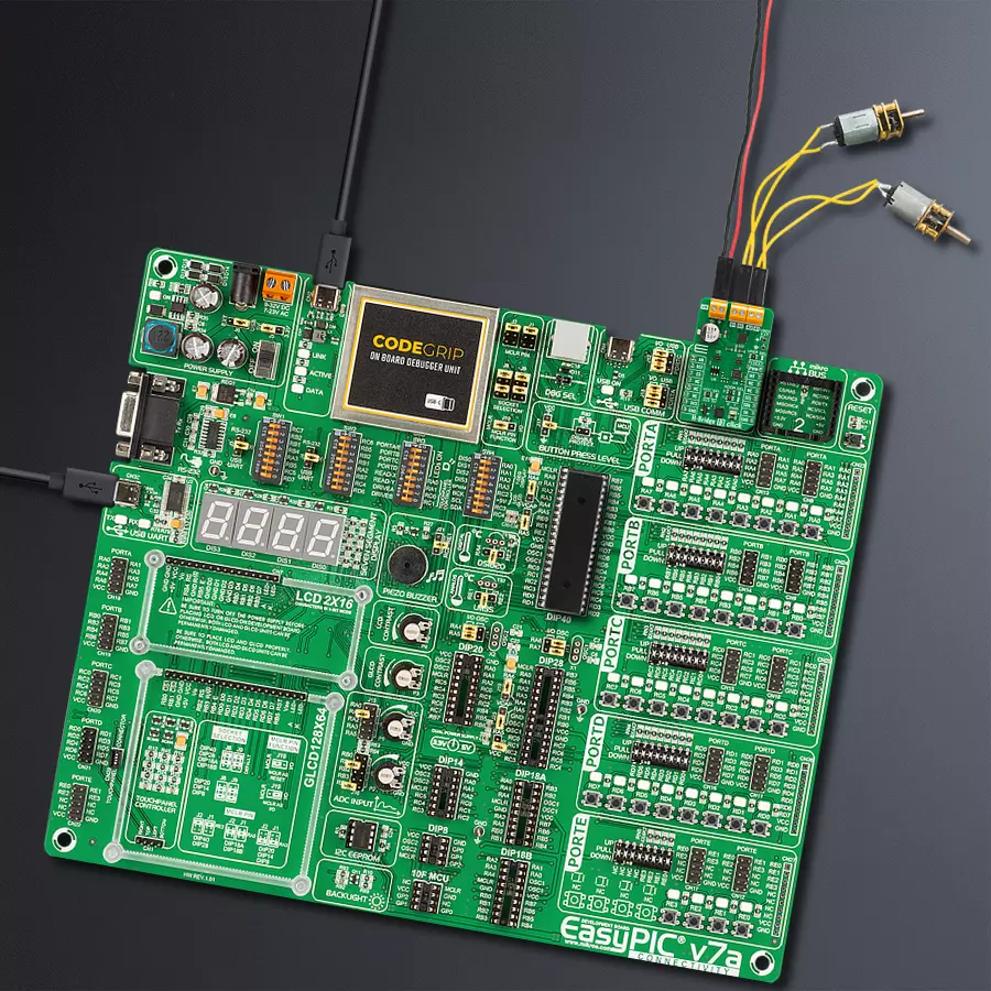
EasyPIC v7a is the seventh generation of PIC development boards specially designed for the needs of rapid development of embedded applications. It supports a wide range of 8-bit PIC microcontrollers from Microchip and has a broad set of unique functions, such as the first-ever embedded debugger/programmer over USB-C. The development board is well organized and designed so that the end-user has all the necessary elements in one place, such as switches, buttons, indicators, connectors, and others. With four different connectors for each port, EasyPIC v7a allows you to connect accessory boards, sensors, and custom electronics more efficiently than ever. Each part of the EasyPIC v7a development board
contains the components necessary for the most efficient operation of the same board. In addition to the advanced integrated CODEGRIP programmer/debugger module, which offers many valuable programming/debugging options and seamless integration with the Mikroe software environment, the board also includes a clean and regulated power supply module for the development board. It can use various external power sources, including an external 12V power supply, 7-23V AC or 9-32V DC via DC connector/screw terminals, and a power source via the USB Type-C (USB-C) connector. Communication options such as USB-UART and RS-232 are also included, alongside the well-
established mikroBUS™ standard, three display options (7-segment, graphical, and character-based LCD), and several different DIP sockets. These sockets cover a wide range of 8-bit PIC MCUs, from PIC10F, PIC12F, PIC16F, PIC16Enh, PIC18F, PIC18FJ, and PIC18FK families. EasyPIC v7a is an integral part of the Mikroe ecosystem for rapid development. Natively supported by Mikroe software tools, it covers many aspects of prototyping and development thanks to a considerable number of different Click boards™ (over a thousand boards), the number of which is growing every day.

Microcontroller Overview
MCU Card / MCU
Architecture
PIC
MCU Memory (KB)
24
Silicon Vendor
Microchip
Pin count
40
RAM (Bytes)
2048
You complete me!
Accessories
DC Gear Motor - 430RPM (3-6V) represents an all-in-one combination of a motor and gearbox, where the addition of gear leads to a reduction of motor speed while increasing the torque output. This gear motor has a spur gearbox, making it a highly reliable solution for applications with lower torque and speed requirements. The most critical parameters for gear motors are speed, torque, and efficiency, which are, in this case, 520RPM with no load and 430RPM at maximum efficiency, alongside a current of 60mA and a torque of 50g.cm. Rated for a 3-6V operational voltage range and clockwise/counterclockwise rotation direction, this motor represents an excellent solution for many functions initially performed by brushed DC motors in robotics, medical equipment, electric door locks, and much more.

Used MCU Pins
mikroBUS™ mapper
Take a closer look
Click board™ Schematic

Step by step
Project assembly

Start by selecting your development board and Click board™. Begin with the EasyPIC v7a as your development board.


Track your results in real time
Application Output
1. Application Output - In Debug mode, the 'Application Output' window enables real-time data monitoring, offering direct insight into execution results. Ensure proper data display by configuring the environment correctly using the provided tutorial.

2. UART Terminal - Use the UART Terminal to monitor data transmission via a USB to UART converter, allowing direct communication between the Click board™ and your development system. Configure the baud rate and other serial settings according to your project's requirements to ensure proper functionality. For step-by-step setup instructions, refer to the provided tutorial.

3. Plot Output - The Plot feature offers a powerful way to visualize real-time sensor data, enabling trend analysis, debugging, and comparison of multiple data points. To set it up correctly, follow the provided tutorial, which includes a step-by-step example of using the Plot feature to display Click board™ readings. To use the Plot feature in your code, use the function: plot(*insert_graph_name*, variable_name);. This is a general format, and it is up to the user to replace 'insert_graph_name' with the actual graph name and 'variable_name' with the parameter to be displayed.

Software Support
Library Description
This library contains API for H-Bridge 13 Click driver.
Key functions:
hbridge13_write_reg- H-Bridge 13 write register function.hbridge13_set_direction- H-Bridge 13 set direction function.hbridge13_get_an_voltage- H-Bridge 13 get xIPROPI voltage function.
Open Source
Code example
The complete application code and a ready-to-use project are available through the NECTO Studio Package Manager for direct installation in the NECTO Studio. The application code can also be found on the MIKROE GitHub account.
/*!
 * @file main.c
 * @brief H-Bridge 13 Click example
 *
 * # Description
 * This example demonstrates the use of the H-Bridge 13 Click board by
 * driving the motor connected to OUT A and OUT B, in both directions with braking and freewheeling.
 *
 * The demo application is composed of two sections :
 *
 * ## Application Init
 * Initializes the driver and performs the Click default configuration.
 *
 * ## Application Task
 * This example is driving a motor in both directions with changes in speed and
 * motor braking and freewheeling in between.
 *
 * @author Stefan Ilic
 *
 */

#include "board.h"
#include "log.h"
#include "hbridge13.h"

static hbridge13_t hbridge13;
static log_t logger;

void application_init ( void )
{
    log_cfg_t log_cfg;  /**< Logger config object. */
    hbridge13_cfg_t hbridge13_cfg;  /**< Click config object. */

    /**
     * Logger initialization.
     * Default baud rate: 115200
     * Default log level: LOG_LEVEL_DEBUG
     * @note If USB_UART_RX and USB_UART_TX
     * are defined as HAL_PIN_NC, you will
     * need to define them manually for log to work.
     * See @b LOG_MAP_USB_UART macro definition for detailed explanation.
     */
    LOG_MAP_USB_UART( log_cfg );
    log_init( &logger, &log_cfg );
    log_info( &logger, " Application Init " );

    // Click initialization.
    hbridge13_cfg_setup( &hbridge13_cfg );
    HBRIDGE13_MAP_MIKROBUS( hbridge13_cfg, MIKROBUS_1 );
    if ( I2C_MASTER_ERROR == hbridge13_init( &hbridge13, &hbridge13_cfg ) )
    {
        log_error( &logger, " Communication init." );
        for ( ; ; );
    }

    if ( HBRIDGE13_ERROR == hbridge13_default_cfg ( &hbridge13 ) )
    {
        log_error( &logger, " Default configuration." );
        for ( ; ; );
    }

    log_info( &logger, " Application Task " );
}

void application_task ( void )
{
    for( uint8_t n_cnt = 0; n_cnt <= 100; n_cnt += 10 )
    {
        log_printf( &logger, " Motor in forward mode with speed of %d %% \r\n", ( uint16_t ) n_cnt );
        hbridge13_set_direction( &hbridge13, HBRIDGE13_DIR_FORWARD, n_cnt );
        Delay_ms ( 1000 );
    }

    log_printf( &logger, " Motor brake is on \r\n" );
    hbridge13_set_brake( &hbridge13 );
    Delay_ms ( 1000 );
    Delay_ms ( 1000 );
    Delay_ms ( 1000 );
    Delay_ms ( 1000 );
    Delay_ms ( 1000 );

    for( uint8_t n_cnt = 0; n_cnt <= 100; n_cnt += 10 )
    {
        log_printf( &logger, " Motor in reverse with speed of %d %% \r\n", ( uint16_t ) n_cnt );
        hbridge13_set_direction( &hbridge13, HBRIDGE13_DIR_REVERSE, n_cnt );
        Delay_ms ( 1000 );
    }

    log_printf( &logger, " Motor is coasting \r\n" );
    hbridge13_set_coast( &hbridge13 );
    Delay_ms ( 1000 );
    Delay_ms ( 1000 );
    Delay_ms ( 1000 );
    Delay_ms ( 1000 );
    Delay_ms ( 1000 );
}

int main ( void )
{
    /* Do not remove this line or clock might not be set correctly. */
    #ifdef PREINIT_SUPPORTED
    preinit();
    #endif

    application_init( );

    for ( ; ; )
    {
        application_task( );
    }

    return 0;
}

// ------------------------------------------------------------------------ END


