Elevate speed detection to new heights with K-LD2 and PIC18LF46K80
Trust our speed detector for reliable, real-time speed insights.
Published Nov 01, 2023
Click board™
Speed Radar Click
Dev. board
EasyPIC v7a
Compiler
NECTO Studio
MCU
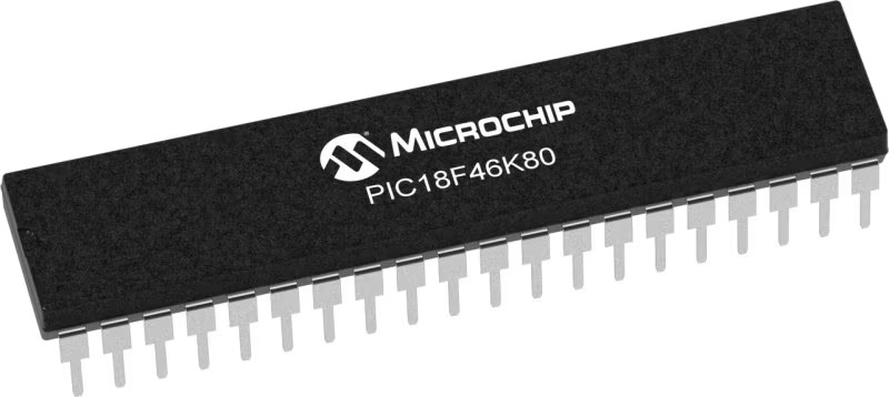
PIC18LF46K80
Our radar solution is the pulse of protection, extending its reach up to 30m for cars and 15m for humans, ensuring a secure and monitored perimeter for enhanced safety.
A
A
Hardware Overview
How does it work?
Speed Radar Click is based on the K-LD2, a radar transceiver from RFbeam. The sensor includes a 2x4 patch radar front-end antenna with an asymmetrical 80°/34° beam aperture and a powerful signal processing unit with two digital outputs for signal detection information. The sensitivity and the hold time are adjustable using analog inputs with 10K potentiometers labeled SENS and TIME. The serial interface features a powerful command set to read out advanced detection data or fully customize the detection algorithm. Its internal I/Q Doppler signal is processed by using a complex fast Fourier transform (FFT) measurement method, which is important in the science of audio and acoustic measurements. This measurement method features easy detection of the direction of a movement, increased detection range with better SNR, efficient interference suppression, and vibration suppression. The signal processing unit samples the analog I/Q Doppler signals of the antenna and calculates a complex FFT in
real-time, after which the noise and interference suppression is done. The detection algorithm looks for valid detection and digital outputs for the length of the hold time setting. I/Q Doppler signals are phase-shifted by +90° or -90° depending on the direction of a movement in the front of the sensor. The Speed Radar Click can work as a standalone or host-driven device. It can detect the speed of any moving object, can filter out slow and fast speeds, and even detect micro speeds (very low speeds). If developing a standalone device, you can set the sensitivity and the hold time by the potentiometers. The sensitivity can be achieved in a range of 0 up to 34dB, approximately 2 to 20 meters for a walking human. The hold time can be set at 0.2 up to 160s. The sensor will filter the interferences and look for a movement with a magnitude higher than the threshold set by the sensitivity. The K-LD2 will output its detection state over the DET pin and the direction over the DIR pin of the mikroBUS™ socket along the appropriate DETECT and DIRECT LEDs. In addition,
Speed Radar Click is equipped with the CP2102N, a USB-to-UART bridge from Silicon Labs, and a USB C connector for connecting this Click board™ to a PC. Speed Radar uses a standard UART interface to communicate with the host MCU with commonly used UART RX and TX pins, supporting a baud rate of 38400bps. It will output a High logic state over the DET pin if there is a detection and a Low if there is not. The direction output will be over the DIR pin with a Low logic state for backward/receding movement and a High logic state for forward/approaching movement. This pin is a digital miscellaneous output and can be configured for many purposes, such as detection, direction, range, and micro-detection. This Click board™ can be operated only with a 3.3V logic voltage level. The board must perform appropriate logic voltage level conversion before using MCUs with different logic levels. Also, it comes equipped with a library containing functions and an example code that can be used as a reference for further development.

Features overview
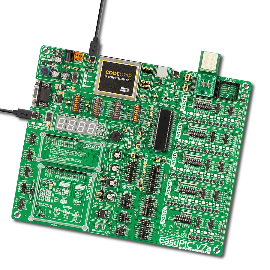
Development board
EasyPIC v7a is the seventh generation of PIC development boards specially designed for the needs of rapid development of embedded applications. It supports a wide range of 8-bit PIC microcontrollers from Microchip and has a broad set of unique functions, such as the first-ever embedded debugger/programmer over USB-C. The development board is well organized and designed so that the end-user has all the necessary elements in one place, such as switches, buttons, indicators, connectors, and others. With four different connectors for each port, EasyPIC v7a allows you to connect accessory boards, sensors, and custom electronics more efficiently than ever. Each part of the EasyPIC v7a development board
contains the components necessary for the most efficient operation of the same board. In addition to the advanced integrated CODEGRIP programmer/debugger module, which offers many valuable programming/debugging options and seamless integration with the Mikroe software environment, the board also includes a clean and regulated power supply module for the development board. It can use various external power sources, including an external 12V power supply, 7-23V AC or 9-32V DC via DC connector/screw terminals, and a power source via the USB Type-C (USB-C) connector. Communication options such as USB-UART and RS-232 are also included, alongside the well-
established mikroBUS™ standard, three display options (7-segment, graphical, and character-based LCD), and several different DIP sockets. These sockets cover a wide range of 8-bit PIC MCUs, from PIC10F, PIC12F, PIC16F, PIC16Enh, PIC18F, PIC18FJ, and PIC18FK families. EasyPIC v7a is an integral part of the Mikroe ecosystem for rapid development. Natively supported by Mikroe software tools, it covers many aspects of prototyping and development thanks to a considerable number of different Click boards™ (over a thousand boards), the number of which is growing every day.

Microcontroller Overview
MCU Card / MCU
Architecture
PIC
MCU Memory (KB)
64
Silicon Vendor
Microchip
Pin count
40
RAM (Bytes)
3648
Used MCU Pins
mikroBUS™ mapper
Take a closer look
Click board™ Schematic

Step by step
Project assembly

Start by selecting your development board and Click board™. Begin with the EasyPIC v7a as your development board.


Track your results in real time
Application Output
1. Application Output - In Debug mode, the 'Application Output' window enables real-time data monitoring, offering direct insight into execution results. Ensure proper data display by configuring the environment correctly using the provided tutorial.

2. UART Terminal - Use the UART Terminal to monitor data transmission via a USB to UART converter, allowing direct communication between the Click board™ and your development system. Configure the baud rate and other serial settings according to your project's requirements to ensure proper functionality. For step-by-step setup instructions, refer to the provided tutorial.

3. Plot Output - The Plot feature offers a powerful way to visualize real-time sensor data, enabling trend analysis, debugging, and comparison of multiple data points. To set it up correctly, follow the provided tutorial, which includes a step-by-step example of using the Plot feature to display Click board™ readings. To use the Plot feature in your code, use the function: plot(*insert_graph_name*, variable_name);. This is a general format, and it is up to the user to replace 'insert_graph_name' with the actual graph name and 'variable_name' with the parameter to be displayed.

Software Support
Library Description
This library contains API for Speed Radar Click driver.
Key functions:
speedradar_send_command- Speed Radar send command function.speedradar_get_direction- Speed Radar get direction function.speedradar_get_detection- Speed Radar get detection function.
Open Source
Code example
The complete application code and a ready-to-use project are available through the NECTO Studio Package Manager for direct installation in the NECTO Studio. The application code can also be found on the MIKROE GitHub account.
/*!
 * @file main.c
 * @brief Speed Radar Click Example.
 *
 * # Description
 * This example demonstrates the use of Speed Radar Click board by processing
 * the incoming data and displaying them on the USB UART.
 *
 * The demo application is composed of two sections :
 *
 * ## Application Init
 * Initializes the driver and performs the Click default configuration.
 *
 * ## Application Task
 * The demo application sends a command that returns and displays the speed [km/h]
 * and magnitude [dB] of the dominant movement for the forward and backward planes of the spectrum,
 * measured frontal to the sensor.
 * Results are being sent to the UART Terminal, where you can track their changes.
 *
 * ## Additional Function
 * - static void speedradar_clear_app_buf ( void )
 * - static err_t speedradar_process ( speedradar_t *ctx )
 * - static void speedradar_adv_det_display ( void )
 *
 * @author Nenad Filipovic
 *
 */

#include "board.h"
#include "log.h"
#include "speedradar.h"

// Application buffer size
#define PROCESS_BUFFER_SIZE        200
#define PROCESS_C00_RSP_LEN        14

// Speed measurement macros
#define NFFT_WIDTH_DEFAULT         256.0
#define FREQUENCY_DEFAULT          44.7
#define COS_ANGLE_OBJECT_VAL       1.0

static speedradar_t speedradar;
static log_t logger;

static uint8_t app_buf[ PROCESS_BUFFER_SIZE ] = { 0 };
static int32_t app_buf_len = 0;

/**
 * @brief Speed Radar clearing application buffer.
 * @details This function clears memory of application buffer and reset its length.
 * @note None.
 */
static void speedradar_clear_app_buf ( void );

/**
 * @brief Speed Radar data reading function.
 * @details This function reads data from device and concatenates data to application buffer.
 * @param[in] ctx : Click context object.
 * See #speedradar_t object definition for detailed explanation.
 * @return @li @c  0 - Read some data.
 *         @li @c -1 - Nothing is read.
 * See #err_t definition for detailed explanation.
 * @note None.
 */
static err_t speedradar_process ( speedradar_t *ctx );

/**
 * @brief Speed Radar advanced detection function.
 * @details This function processes and displays the response data of the detection string command.
 * @note The valid speed of the object is when it is measured frontal to the sensor.
 * An angle between the object and the sensor reduces the dominant movement speed.
 */
static void speedradar_adv_det_display ( void );

void application_init ( void )
{
    log_cfg_t log_cfg;  /**< Logger config object. */
    speedradar_cfg_t speedradar_cfg;  /**< Click config object. */

    /**
     * Logger initialization.
     * Default baud rate: 115200
     * Default log level: LOG_LEVEL_DEBUG
     * @note If USB_UART_RX and USB_UART_TX
     * are defined as HAL_PIN_NC, you will
     * need to define them manually for log to work.
     * See @b LOG_MAP_USB_UART macro definition for detailed explanation.
     */
    LOG_MAP_USB_UART( log_cfg );
    log_init( &logger, &log_cfg );
    log_info( &logger, " Application Init " );

    // Click initialization.
    speedradar_cfg_setup( &speedradar_cfg );
    SPEEDRADAR_MAP_MIKROBUS( speedradar_cfg, MIKROBUS_1 );
    if ( UART_ERROR == speedradar_init( &speedradar, &speedradar_cfg ) )
    {
        log_error( &logger, " Communication init." );
        for ( ; ; );
    }
    Delay_ms ( 100 );

    if ( SPEEDRADAR_ERROR == speedradar_default_cfg ( &speedradar ) )
    {
        log_error( &logger, " Default configuration." );
        for ( ; ; );
    }
    Delay_ms ( 100 );

    speedradar_process( &speedradar );
    speedradar_clear_app_buf( );
    Delay_ms ( 100 );
    log_info( &logger, " Application Task " );
    log_printf( &logger, " ---------------------- \r\n" );
    Delay_ms ( 100 );
}

void application_task ( void )
{
    speedradar_send_command( &speedradar, SPEEDRADAR_CMD_GET_DETECTION_STR );
    Delay_ms ( 50 );
    speedradar_process( &speedradar );
    if ( app_buf_len >= PROCESS_C00_RSP_LEN  )
    {
        speedradar_adv_det_display( );
        speedradar_clear_app_buf( );
        Delay_ms ( 100 );
    }
}

int main ( void )
{
    /* Do not remove this line or clock might not be set correctly. */
    #ifdef PREINIT_SUPPORTED
    preinit();
    #endif

    application_init( );

    for ( ; ; )
    {
        application_task( );
    }

    return 0;
}

static void speedradar_clear_app_buf ( void )
{
    memset( app_buf, 0, app_buf_len );
    app_buf_len = 0;
}

static err_t speedradar_process ( speedradar_t *ctx )
{
    uint8_t rx_buf[ PROCESS_BUFFER_SIZE ] = { 0 };
    int32_t rx_size = 0;
    rx_size = speedradar_generic_read( ctx, rx_buf, PROCESS_BUFFER_SIZE );
    if ( rx_size > 0 )
    {
        int32_t buf_cnt = app_buf_len;
        if ( ( ( app_buf_len + rx_size ) > PROCESS_BUFFER_SIZE ) && ( app_buf_len > 0 ) )
        {
            buf_cnt = PROCESS_BUFFER_SIZE - ( ( app_buf_len + rx_size ) - PROCESS_BUFFER_SIZE );
            memmove ( app_buf, &app_buf[ PROCESS_BUFFER_SIZE - buf_cnt ], buf_cnt );
        }
        for ( int32_t rx_cnt = 0; rx_cnt < rx_size; rx_cnt++ )
        {
            if ( rx_buf[ rx_cnt ] )
            {
                app_buf[ buf_cnt++ ] = rx_buf[ rx_cnt ];
                if ( app_buf_len < PROCESS_BUFFER_SIZE )
                {
                    app_buf_len++;
                }
            }
        }
        return SPEEDRADAR_OK;
    }
    return SPEEDRADAR_ERROR;
}

static void speedradar_adv_det_display ( void )
{
    if ( strncmp( SPEEDRADAR_ERR_MSG, app_buf, 3 ) )
    {
        uint8_t detection = 0, speed = 0, magnitude = 0;
        float speed_km_h = 0;
        detection = ( app_buf[ 0 ] - SPEEDRADAR_ASCII_CHAR_0 ) * SPEEDRADAR_MLP_HUNDREDS +
                    ( app_buf[ 1 ] - SPEEDRADAR_ASCII_CHAR_0 ) * SPEEDRADAR_MLP_TENS  +
                    ( app_buf[ 2 ] - SPEEDRADAR_ASCII_CHAR_0 );
        speed     = ( app_buf[ 4 ] - SPEEDRADAR_ASCII_CHAR_0 ) * SPEEDRADAR_MLP_HUNDREDS +
                    ( app_buf[ 5 ] - SPEEDRADAR_ASCII_CHAR_0 ) * SPEEDRADAR_MLP_TENS  +
                    ( app_buf[ 6 ] - SPEEDRADAR_ASCII_CHAR_0 );
        magnitude = ( app_buf[ 8 ] - SPEEDRADAR_ASCII_CHAR_0 ) * SPEEDRADAR_MLP_HUNDREDS +
                    ( app_buf[ 9 ] - SPEEDRADAR_ASCII_CHAR_0 ) * SPEEDRADAR_MLP_TENS  +
                    ( app_buf[ 10 ] - SPEEDRADAR_ASCII_CHAR_0 );

        if ( SPEEDRADAR_R00_DET_VALID & detection )
        {
            speed_km_h = ( float ) speed;
            speed_km_h *= SPEEDRADAR_SAMPLING_RATE_5120_HZ;
            speed_km_h /= NFFT_WIDTH_DEFAULT;
            speed_km_h /= FREQUENCY_DEFAULT;
            speed_km_h /= COS_ANGLE_OBJECT_VAL;
            if ( SPEEDRADAR_R00_DIR_FORWARD & detection )
            {
                log_printf( &logger, " Speed: +%.2f [km/h]\r\n", speed_km_h );
                log_printf( &logger, " Magnitude: +%d [dB] \r\n", ( uint16_t ) magnitude );
            }
            else
            {
                log_printf( &logger, " Speed: -%.2f [km/h]\r\n", speed_km_h );
                log_printf( &logger, " Magnitude: -%d [dB] \r\n", ( uint16_t ) magnitude );

            }
        }
        else
        {
            log_printf( &logger, " No target found!\r\n" );
        }
        log_printf( &logger, " ---------------------- \r\n" );
    }
    else
    {
        speedradar_clear_app_buf( );
    }
}

// ------------------------------------------------------------------------ END


