Open doors to new possibilities in IoT communication with LR1110 and PIC18F4550
Connecting the unreachable

Published Nov 01, 2023
Click board™
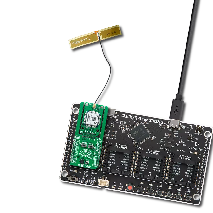
LR IoT Click
Dev. board
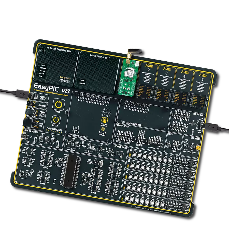
EasyPIC v7a
Compiler
NECTO Studio
MCU
PIC18F4550
LR IoT represents the future of connectivity, a long-range revolution that opens doors to new possibilities in IoT communication
A
A
Hardware Overview
How does it work?
LR IoT Click is based on the LR1110, a long-range, ultra-low power transceiver from Semtech Corporation designed to enhance LoRa®-based geolocation applications. This platform solution supports LoRa® and (G)FSK modulations for LPWAN use cases over the active 868/915MHz ISM band antenna, which Mikroe also offers. The LR1110 also features a low-power multi-band front-end that can acquire several signals of opportunity for geolocation purposes (802.11b/g/n WiFi AP MAC addresses, GNSS (GPS, BeiDou) satellites signals) and then transmit them using LPWAN network to a geolocation server, which computes the position of the object. This Click board™ is optimized for low-power applications requiring indoor and outdoor geolocation, such as asset location, traceability, loss and theft prevention, asset recovery, and inventory management. The LR1110 uses three operating modes: WiFi passive scanning and two GNSS modes for outdoor geolocation, such as GNSS autonomous and assisted modes. With WiFi passive scanning, the LR1110 can discover the WiFi b/g/n access points available near the device and extract MAC addresses to geolocate them. The objective is to
obtain at least 2 MAC addresses and position the device after being sent to an online WiFi lookup service. The WiFi passive scanning implemented in LR1110 can also extract the country code information of an access point contained in the beacon or probe response. In addition to WiFi, there is a fast and low-power GNSS scanner, which, with an active GNSS antenna from our offer, captures a short portion of the signal broadcast by the GNSS satellites and extracts the information required to calculate the device position. This information is then aggregated into an NAV message, which can be sent to a back-end system to compute the device position. As mentioned before, the GNSS scanner has two modes of operation: autonomous and assisted. In autonomous mode, which does not require any assistance data, the LR1110 searches and decodes the signal from the strong satellites for indoor/outdoor detection, while in the assisted mode, allows searching for all the visible satellites and also requires connectivity with the geolocation server for calculation of the device position. This Click board™ communicates with an MCU through a standard SPI interface supporting
the most common SPI mode, SPI Mode 0, with a maximum frequency of 16MHz. It also possesses an interrupt pin, routed to the INT pin of the mikroBUS™ socket, allowing the host MCU to react to special events in the LR1110 system without register-poll. A “BUSY” indicator, labeled as BSY and routed to the PWM pin of the mikroBUS™ socket, indicating that the internal MCU can’t receive any commands from the host MCU, and general reset function routed on the RST pin of the mikroBUS™ socket as well as on the onboard RESET button. It also uses two LED indicators labeled STAT1 and STAT2 for optional GNSS and WiFi network-activity status visual indications. Still, they can also be configured according to the wishes and needs of the user himself. This Click board™ can be operated only with a 3.3V logic voltage level. The board must perform appropriate logic voltage level conversion before using MCUs with different logic levels. Also, it comes equipped with a library containing functions and an example code that can be used as a reference for further development.

Features overview
Development board
EasyPIC v7a is the seventh generation of PIC development boards specially designed for the needs of rapid development of embedded applications. It supports a wide range of 8-bit PIC microcontrollers from Microchip and has a broad set of unique functions, such as the first-ever embedded debugger/programmer over USB-C. The development board is well organized and designed so that the end-user has all the necessary elements in one place, such as switches, buttons, indicators, connectors, and others. With four different connectors for each port, EasyPIC v7a allows you to connect accessory boards, sensors, and custom electronics more efficiently than ever. Each part of the EasyPIC v7a development board
contains the components necessary for the most efficient operation of the same board. In addition to the advanced integrated CODEGRIP programmer/debugger module, which offers many valuable programming/debugging options and seamless integration with the Mikroe software environment, the board also includes a clean and regulated power supply module for the development board. It can use various external power sources, including an external 12V power supply, 7-23V AC or 9-32V DC via DC connector/screw terminals, and a power source via the USB Type-C (USB-C) connector. Communication options such as USB-UART and RS-232 are also included, alongside the well-
established mikroBUS™ standard, three display options (7-segment, graphical, and character-based LCD), and several different DIP sockets. These sockets cover a wide range of 8-bit PIC MCUs, from PIC10F, PIC12F, PIC16F, PIC16Enh, PIC18F, PIC18FJ, and PIC18FK families. EasyPIC v7a is an integral part of the Mikroe ecosystem for rapid development. Natively supported by Mikroe software tools, it covers many aspects of prototyping and development thanks to a considerable number of different Click boards™ (over a thousand boards), the number of which is growing every day.

Microcontroller Overview
MCU Card / MCU
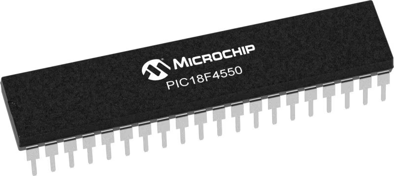
Architecture
PIC
MCU Memory (KB)
32
Silicon Vendor
Microchip
Pin count
40
RAM (Bytes)
2048
You complete me!
Accessories
868MHz right-angle rubber antenna is a compact and versatile solution for wireless communication. Operating within the frequency range of 868-915MHz, it ensures optimal signal reception and transmission. With a 50-ohm impedance, it's compatible with various devices and systems. This antenna boasts a 2dB gain, enhancing signal strength and extending communication range. Its vertical polarization further contributes to signal clarity. Designed to handle up to 50W of input power, it's a robust choice for various applications. Measuring just 48mm in length, this antenna is both discreet and practical. Its SMA male connector ensures a secure and reliable connection to your equipment. Whether you're working with IoT devices, remote sensors, or other wireless technologies, the 868MHz right-angle antenna offers the performance and flexibility you need for seamless communication.

This GPS Active Embedded Antenna is an excellent choice for all GPS/GNSS Click boards™ from our offer. With its high gain and active band filtering, it is a perfect choice when reinforced positioning is required. It can be mounted on the PCB directly. The GPS/GNSS module features a small cable with 10cm in length, allowing it to be positioned away from a small IPEX connector.

WiFi Rubber 2.4GHz Antenna is a versatile accessory designed for Click board™ applications featuring WiFi modules. This antenna is tailor-made to enhance wireless connectivity, making it an essential choice for developers and engineers. Featuring a right-angle SMA male connector at its tip, the antenna offers seamless integration with Click boards™ or female SMA module connectors. This user-friendly design simplifies installation and ensures flexibility in various setups. Operating within the 2400-2500MHz frequency range, this antenna guarantees reliable connectivity across a broad spectrum of WiFi networks. Its 50-Ohm impedance facilitates efficient signal transfer, while the 2dB gain significantly enhances signal strength and range. With a 100MHz bandwidth, it easily accommodates data transfer and communication stability. Vertical polarization further improves signal reception capabilities. The antenna can handle a maximum input power of 50W, making it suitable for high-power applications without compromising performance. Its compact 50mm length ensures a discreet and unobtrusive presence. Whether you're designing IoT devices, smart home applications, or industrial equipment, the WiFi Rubber Antenna, with its SMA male connector, is the ideal choice to ensure optimal wireless connectivity. It's a powerful tool that keeps your devices reliably connected and communicating effectively in wireless technology.

IPEX-SMA cable is a type of RF (radio frequency) cable assembly. "IPEX" refers to the IPEX connector, a miniature coaxial connector commonly used in small electronic devices. "SMA" stands for SubMiniature Version A and is another coaxial connector commonly used in RF applications. An IPEX-SMA cable assembly has an IPEX connector on one end and an SMA connector on the other, allowing it to connect devices or components that use these specific connectors. These cables are often used in applications like WiFi or cellular antennas, GPS modules, and other RF communication systems where a reliable and low-loss connection is required.

Used MCU Pins
mikroBUS™ mapper
Take a closer look
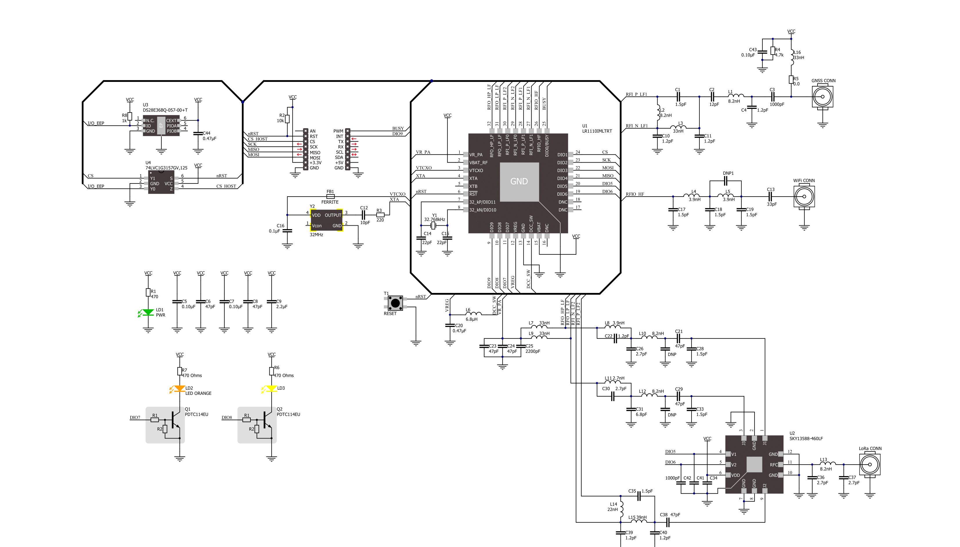
Click board™ Schematic
Step by step
Project assembly

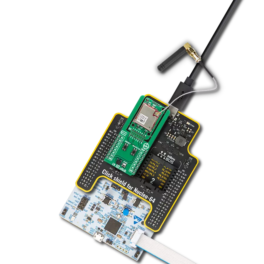
Start by selecting your development board and Click board™. Begin with the EasyPIC v7a as your development board.


Software Support
Library Description
This library contains API for LR IoT Click driver.
Key functions:
lriot_get_wifi_scan_results- This function performs a WiFi scanning and reads the resultslriot_get_gnss_scan_results- This function performs a GNSS scanning and reads the resultslriot_send_lora_message- This function sends a LoRa message to the receiver
Open Source
Code example
The complete application code and a ready-to-use project are available through the NECTO Studio Package Manager for direct installation in the NECTO Studio. The application code can also be found on the MIKROE GitHub account.
/*!
 * @file main.c
 * @brief LR IoT Click example
 *
 * # Description
 * This example demonstrates the use of LR IoT Click board by reading a GNSS and WiFi
 * scanning results and displaying it on the USB UART. In the case of a tranceive firmware
 * the communication between two devices over LoRa will be demonstrated as well.
 *
 * The demo application is composed of two sections :
 *
 * ## Application Init
 * Initializes the driver, performs the Click default configuration, and after that reads
 * and displays the chip's firmware information. In the case you need to update or change the default
 * firmware refer to the @b LRIOT_UPDATE_FIRMWARE and @b LRIOT_FIRMWARE_SELECTOR macro definition.
 *
 * ## Application Task
 * There are 3 types of the example:
 * 1. Modem firmware: reads a GNSS and WiFi scanning results and displays them on the USB UART.
 * 2. Transcever firmware (application mode transmitter ): reads a GNSS and WiFi scanning results
 *    as well as the chip internal temperature and sends specific LoRa messages containing that information
 *    to the LoRa receiver.
 * 3. Transcever firmware (application mode receiver): reads all incoming LoRa packets and displays them
 *    on the USB UART.
 *
 * @author Stefan Filipovic
 *
 */
#include "board.h"
#include "log.h"
#include "lriot.h"
#include "conversions.h"

static lriot_t lriot;
static log_t logger;

#if ( LRIOT_FIRMWARE_SELECTOR == LRIOT_TRANSCEIVE_FIRMWARE )
// Comment out the line below in order to switch the application mode to receiver
#define DEMO_APP_TRANSMITTER
#endif

/**
 * @brief LR IoT display gnss scan results function.
 * @details This function parses a GNSS scan results object and displays it on the USB UART.
 * @param[in] results : GNSS scan results object.
 * See #lriot_gnss_scan_results_t object definition for detailed explanation.
 * @return None.
 * @note None.
 */
static void lriot_display_gnss_scan_results ( lriot_gnss_scan_results_t results );

/**
 * @brief LR IoT display wifi scan results function.
 * @details This function parses a WiFi scan results object and displays it on the USB UART.
 * @param[in] results : WiFi scan results object.
 * See #lriot_wifi_scan_results_t object definition for detailed explanation.
 * @return None.
 * @note None.
 */
static void lriot_display_wifi_scan_results ( lriot_wifi_scan_results_t results );

/**
 * @brief LR IoT display chip info function.
 * @details This function parses a chip firmware information object and displays it on the USB UART.
 * @param[in] info : Chip information object.
 * See #lriot_chip_info_t object definition for detailed explanation.
 * @return None.
 * @note None.
 */
static void lriot_display_chip_info ( lriot_chip_info_t info );

void application_init ( void )
{
    log_cfg_t log_cfg;      /**< Logger config object. */
    lriot_cfg_t lriot_cfg;  /**< Click config object. */

    /**
     * Logger initialization.
     * Default baud rate: 115200
     * Default log level: LOG_LEVEL_DEBUG
     * @note If USB_UART_RX and USB_UART_TX
     * are defined as HAL_PIN_NC, you will
     * need to define them manually for log to work.
     * See @b LOG_MAP_USB_UART macro definition for detailed explanation.
     */
    LOG_MAP_USB_UART( log_cfg );
    log_init( &logger, &log_cfg );
    log_info( &logger, " Application Init " );

    // Click initialization.
    lriot_cfg_setup( &lriot_cfg );
    LRIOT_MAP_MIKROBUS( lriot_cfg, MIKROBUS_1 );

    if ( SPI_MASTER_ERROR == lriot_init( &lriot, &lriot_cfg ) )
    {
        log_error( &logger, " Communication init." );
        for ( ; ; );
    }

    if ( LRIOT_ERROR == lriot_default_cfg ( &lriot ) )
    {
        log_error( &logger, " Default configuration." );
        for ( ; ; );
    }

    lriot_chip_info_t chip_info;
    if ( LRIOT_OK == lriot_get_chip_info ( &lriot, &chip_info ) )
    {
        lriot_display_chip_info ( chip_info );
    }

    log_info( &logger, " Application Task " );
}

void application_task ( void )
{
#if ( LRIOT_FIRMWARE_SELECTOR == LRIOT_TRANSCEIVE_FIRMWARE )
    uint8_t lora_buffer[ LRIOT_LORA_PKT_PAYLOAD_LEN ] = { 0 };
    #ifdef DEMO_APP_TRANSMITTER
        lriot_gnss_scan_results_t gnss_results = { 0 };
        lriot_wifi_scan_results_t wifi_results = { 0 };
        uint8_t tmp_buf[ 30 ] = { 0 };
        float temperature = 0;

        if ( LRIOT_OK == lriot_get_gnss_scan_results ( &lriot, &gnss_results ) )
        {
            lriot_display_gnss_scan_results ( gnss_results );
        }

        memset( lora_buffer, 0, sizeof ( lora_buffer ) );
        strcpy( lora_buffer, "Number of sattelites found is " );
        uint16_to_str ( gnss_results.num_satellites, tmp_buf );
        l_trim ( tmp_buf );
        strcat( lora_buffer, tmp_buf );
        if ( LRIOT_OK == lriot_send_lora_message ( &lriot, lora_buffer ) )
        {
            log_printf( &logger, "Send LoRa message - done\r\n" );
        }

        if ( LRIOT_OK == lriot_get_wifi_scan_results ( &lriot, &wifi_results ) )
        {
            lriot_display_wifi_scan_results ( wifi_results );
        }
        memset( lora_buffer, 0, sizeof ( lora_buffer ) );
        strcpy( lora_buffer, "Number of WiFi scan results is " );
        uint16_to_str ( wifi_results.num_wifi_results, tmp_buf );
        l_trim ( tmp_buf );
        strcat( lora_buffer, tmp_buf );
        if ( LRIOT_OK == lriot_send_lora_message ( &lriot, lora_buffer ) )
        {
            log_printf( &logger, "Send LoRa message - done\r\n" );
        }

        log_printf ( &logger, "**************************************************************\r\n" );
        if ( LRIOT_OK == lriot_get_temperature ( &lriot, &temperature ) )
        {
            log_printf ( &logger, "Temperature : %.2f degC\r\n", temperature );
        }
        memset( lora_buffer, 0, sizeof ( lora_buffer ) );
        strcpy( lora_buffer, "My temperature is " );
        float_to_str ( temperature, tmp_buf );
        l_trim ( tmp_buf );
        tmp_buf[ 5 ] = 0;
        strcat( lora_buffer, tmp_buf );
        strcat( lora_buffer, " degC" );
        if ( LRIOT_OK == lriot_send_lora_message ( &lriot, lora_buffer ) )
        {
            log_printf( &logger, "Send LoRa message - done\r\n" );
        }
    #else
        lriot_lora_packet_status_t pkt_status;
        if ( LRIOT_OK == lriot_read_lora_message ( &lriot, &pkt_status, lora_buffer ) )
        {
            log_printf ( &logger, "**************************************************************\r\n" );
            log_printf ( &logger, "*                      RECEIVED LORA PACKET                  *\r\n" );
            log_printf ( &logger, "**************************************************************\r\n" );
            log_printf ( &logger, " RSSI        : %d dBm\r\n", ( uint16_t ) pkt_status.rssi_pkt_in_dbm );
            log_printf ( &logger, " Signal RSSI : %d dBm\r\n", ( uint16_t ) pkt_status.signal_rssi_pkt_in_dbm );
            log_printf ( &logger, " SNR         : %d dB\r\n", ( uint16_t ) pkt_status.snr_pkt_in_db );
            log_printf ( &logger, " Message     : \"%s\"\r\n\n", lora_buffer );
        }
    #endif
#else
    lriot_gnss_scan_results_t gnss_results = { 0 };
    lriot_wifi_scan_results_t wifi_results = { 0 };

    if ( LRIOT_OK == lriot_get_gnss_scan_results ( &lriot, &gnss_results ) )
    {
        lriot_display_gnss_scan_results ( gnss_results );
    }

    if ( LRIOT_OK == lriot_get_wifi_scan_results ( &lriot, &wifi_results ) )
    {
        lriot_display_wifi_scan_results ( wifi_results );
    }
#endif
}

int main ( void )
{
    /* Do not remove this line or clock might not be set correctly. */
    #ifdef PREINIT_SUPPORTED
    preinit();
    #endif

    application_init( );

    for ( ; ; )
    {
        application_task( );
    }

    return 0;
}

static void lriot_display_gnss_scan_results ( lriot_gnss_scan_results_t results )
{
    log_printf ( &logger, "**************************************************************\r\n" );
    log_printf ( &logger, "*                      GNSS SCAN RESULTS                     *\r\n" );
    log_printf ( &logger, "**************************************************************\r\n" );
    log_printf ( &logger, "Number of satellites found: %u\r\n", ( uint16_t ) results.num_satellites );

#if ( LRIOT_FIRMWARE_SELECTOR == LRIOT_TRANSCEIVE_FIRMWARE )
    for ( uint8_t cnt = 0; cnt < results.num_satellites; cnt++ )
    {
        log_printf ( &logger, "{\r\n\tSatellite ID : %u", results.satellite_id_cnr_doppler[ cnt ].satellite_id );
        log_printf ( &logger, "\r\n\tC/N0         : %d dB-Hz", results.satellite_id_cnr_doppler[ cnt ].cnr );
        log_printf ( &logger, "\r\n\tSV doppler   : %d Hz\r\n},\r\n", results.satellite_id_cnr_doppler[ cnt ].doppler );
    }
#else
    for ( uint8_t cnt = 0; cnt < results.num_satellites; cnt++ )
    {
        log_printf ( &logger, "{\r\n\tSatellite ID : %u", results.satellite_id_cnr[ cnt ].satellite_id );
        log_printf ( &logger, "\r\n\tC/N0         : %d dB-Hz\r\n},\r\n", results.satellite_id_cnr[ cnt ].cnr );
    }
#endif
    if ( ( results.scan_results_len > 0 ) &&
         ( LR1110_GNSS_DESTINATION_SOLVER == results.destination_id ) )
    {
        log_printf ( &logger, "NAV message : " );
        for ( uint16_t cnt = 0; cnt < results.scan_results_len; cnt++ )
        {
            log_printf ( &logger, "%.2X", results.scan_results[ cnt ] );
        }
        log_printf ( &logger, "\r\n" );
    }
}

static void lriot_display_wifi_scan_results ( lriot_wifi_scan_results_t results )
{
    log_printf ( &logger, "**************************************************************\r\n" );
    log_printf ( &logger, "*                      WiFi SCAN RESULTS                     *\r\n" );
    log_printf ( &logger, "**************************************************************\r\n" );
    log_printf ( &logger, "Number of WiFi results: %u\r\n", ( uint16_t ) results.num_wifi_results );

    for ( uint8_t i = 0; i < results.num_wifi_results; i++ )
    {
        log_printf ( &logger, "{\r\n\tSSID   : \"%s\",\r\n\tMAC    : \"", results.scan_results[ i ].ssid_bytes );
        for ( uint16_t j = 0; j < LR1110_WIFI_MAC_ADDRESS_LENGTH; j++ )
        {
            log_printf ( &logger, "%.2x", ( uint16_t ) results.scan_results[ i ].mac_address_2[ j ] );
            if ( j < ( LR1110_WIFI_MAC_ADDRESS_LENGTH - 1 ) )
            {
                log_printf ( &logger, ":" );
            }
        }
        log_printf ( &logger, "\",\r\n\tChannel: %u,\r\n", ( int16_t ) results.scan_results[ i ].current_channel );
        log_printf ( &logger, "\tType   : %u,\r\n", ( int16_t ) results.scan_results[ i ].data_rate_info_byte );
        log_printf ( &logger, "\tRSSI   : %d dBm\r\n},\r\n", ( int16_t ) results.scan_results[ i ].rssi );
    }
    log_printf ( &logger, "Scanning time : %d ms\r\n",
                 ( results.timings.demodulation_us + results.timings.rx_capture_us +
                   results.timings.rx_correlation_us + results.timings.rx_detection_us ) / 1000 );
}

static void lriot_display_chip_info ( lriot_chip_info_t info )
{
    log_printf ( &logger, "**************************************************************\r\n");
    log_printf ( &logger, "*                          CHIP INFO                         *\r\n");
    log_printf ( &logger, "**************************************************************\r\n");

#if ( LRIOT_FIRMWARE_SELECTOR == LRIOT_TRANSCEIVE_FIRMWARE )
    log_printf ( &logger, "HARDWARE   : 0x%.2X\r\n", ( uint16_t ) info.version.hw );
    log_printf ( &logger, "TYPE       : 0x%.2X\r\n", ( uint16_t ) info.version.type );
    log_printf ( &logger, "FIRMWARE   : 0x%.4X\r\n", info.version.fw );

    log_printf ( &logger, "UID        : " );
    for ( uint8_t cnt = 0; cnt < ( LR1110_SYSTEM_UID_LENGTH - 1 ); cnt++ )
    {
        log_printf ( &logger, "%.2X-", ( uint16_t ) info.uid[ cnt ] );
    }
    log_printf ( &logger, "%.2X\r\n", ( uint16_t ) info.uid[ LR1110_SYSTEM_UID_LENGTH - 1 ] );
    log_printf ( &logger, "JOIN EUI   : " );
    for ( uint8_t cnt = 0; cnt < ( LR1110_SYSTEM_JOIN_EUI_LENGTH - 1 ); cnt++ )
    {
        log_printf ( &logger, "%.2X-", ( uint16_t ) info.join_eui[ cnt ] );
    }
    log_printf ( &logger, "%.2X\r\n", ( uint16_t ) info.join_eui[ LR1110_SYSTEM_JOIN_EUI_LENGTH - 1 ] );
    log_printf ( &logger, "PIN        : " );
    for ( uint8_t cnt = 0; cnt < LR1110_SYSTEM_PIN_LENGTH; cnt++ )
    {
        log_printf ( &logger, "%.2X", ( uint16_t ) info.pin[ cnt ] );
    }
    log_printf ( &logger, "\r\n\n" );
#else
    log_printf ( &logger, "BOOTLOADER : 0x%.8LX\r\n", info.version.bootloader );
    log_printf ( &logger, "FIRMWARE   : 0x%.8LX\r\n", info.version.firmware );
    log_printf ( &logger, "LORAWAN    : 0x%.4X\r\n", info.version.lorawan );

    log_printf ( &logger, "CHIP EUI   : " );
    for ( uint8_t cnt = 0; cnt < ( LR1110_MODEM_CHIP_EUI_LENGTH - 1 ); cnt++ )
    {
        log_printf ( &logger, "%.2X-", ( uint16_t ) info.chip_eui[ cnt ] );
    }
    log_printf ( &logger, "%.2X\r\n", ( uint16_t ) info.chip_eui[ LR1110_MODEM_CHIP_EUI_LENGTH - 1 ] );
    log_printf ( &logger, "DEV EUI    : " );
    for ( uint8_t cnt = 0; cnt < ( LR1110_MODEM_DEV_EUI_LENGTH - 1 ); cnt++ )
    {
        log_printf ( &logger, "%.2X-", ( uint16_t ) info.dev_eui[ cnt ] );
    }
    log_printf ( &logger, "%.2X\r\n", ( uint16_t ) info.dev_eui[ LR1110_MODEM_DEV_EUI_LENGTH - 1 ] );
    log_printf ( &logger, "JOIN EUI   : " );
    for ( uint8_t cnt = 0; cnt < ( LR1110_MODEM_JOIN_EUI_LENGTH - 1 ); cnt++ )
    {
        log_printf ( &logger, "%.2X-", ( uint16_t ) info.join_eui[ cnt ] );
    }
    log_printf ( &logger, "%.2X\r\n", ( uint16_t ) info.join_eui[ LR1110_MODEM_JOIN_EUI_LENGTH - 1 ] );
    log_printf ( &logger, "PIN        : %.8LX\r\n\n", info.pin );
#endif
}

// ------------------------------------------------------------------------ END