Receive and interpret signals within selected frequency bands with MAX41470 and PIC18F46K42
Efficiency meets security: Sub-GHz RF receiver for all your access needs

Published Nov 09, 2023
Click board™
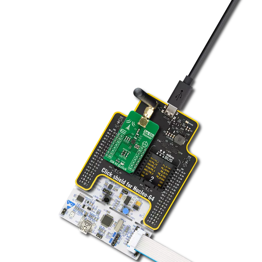
ISM RX 3 Click
Dev. board
EasyPIC v7a
Compiler
NECTO Studio
MCU
PIC18F46K42
Achieve seamless wireless connectivity in diverse applications, allowing for the exchange of information and data across different environments.
A
A
Hardware Overview
How does it work?
ISM RX 3 Click is based on the MAX41470, a sub-GHz ISM RF receiver from Analog Devices. This IC is designed to receive ASK/OOK or FSK/GFSK modulated data in the 287MHz to 320MHz (nominally 315MHz), 425MHz to 480MHz (nominally 434MHz), and 860MHz to 960MHz (nominally 868MHz or 915MHz) ISM frequency bands, using an onboard 16MHz crystal. This Click board™ comes with an ASK modulation and 433.92MHz with a 5bps data rate as its default configuration. Its additional features also include automatic gain control (AGC), a received signal strength indicator (RSSI), automatic frequency control (AFC), and a frequency error indicator (FEI). The MAX41470 has four power states: Shutdown, Sleep, Standby, and Receive-Active. Its Power-Down pin labeled PDN and routed to the RST pin of the mikroBUS™ socket optimizes power consumption used for power ON/OFF
purposes. When the device is enabled (the PDN pin is set to a low logic state), the device's operational states are controlled through the serial interface by the internal registers. This Click board™ communicates with MCU through a standard SPI interface that enables very high clock speeds up to 20MHz, supporting the most common SPI mode, SPI Mode 3, to program the internal registers for complete control of the MAX41470. When in programming mode, the MAX41470 can support a self-polling operation to provide an interrupt signal on the DAT pin routed to the AN pin of the mikroBUS™ socket. The MAX41470 comes only with one data pin for register programming, both data input/output pins. For that purpose, this Click board™ uses the 74LVC1G3157 multiplexer to avoid conflict with other functions driven by the same pin, enabling both writing and reading via the SPI
interface and the 4-wire SPI interface. The selection of the multiplexer channel, more precisely the MISO or MOSI line, is chosen by a logic level on the S line of the multiplexer, set by an SW pin routed to the PWM pin of the mikroBUS™ socket. ISM RX 3 Click possesses the SMA antenna connector with an impedance of 50Ω, which can be used to connect the appropriate antenna that Mikroe offers for improved range and received signal strength. This Click board™ can be operated only with a 3.3V logic voltage level. The board must perform appropriate logic voltage level conversion before using MCUs with different logic levels. Also, it comes equipped with a library containing functions and an example code that can be used as a reference for further development.

Features overview
Development board
EasyPIC v7a is the seventh generation of PIC development boards specially designed for the needs of rapid development of embedded applications. It supports a wide range of 8-bit PIC microcontrollers from Microchip and has a broad set of unique functions, such as the first-ever embedded debugger/programmer over USB-C. The development board is well organized and designed so that the end-user has all the necessary elements in one place, such as switches, buttons, indicators, connectors, and others. With four different connectors for each port, EasyPIC v7a allows you to connect accessory boards, sensors, and custom electronics more efficiently than ever. Each part of the EasyPIC v7a development board
contains the components necessary for the most efficient operation of the same board. In addition to the advanced integrated CODEGRIP programmer/debugger module, which offers many valuable programming/debugging options and seamless integration with the Mikroe software environment, the board also includes a clean and regulated power supply module for the development board. It can use various external power sources, including an external 12V power supply, 7-23V AC or 9-32V DC via DC connector/screw terminals, and a power source via the USB Type-C (USB-C) connector. Communication options such as USB-UART and RS-232 are also included, alongside the well-
established mikroBUS™ standard, three display options (7-segment, graphical, and character-based LCD), and several different DIP sockets. These sockets cover a wide range of 8-bit PIC MCUs, from PIC10F, PIC12F, PIC16F, PIC16Enh, PIC18F, PIC18FJ, and PIC18FK families. EasyPIC v7a is an integral part of the Mikroe ecosystem for rapid development. Natively supported by Mikroe software tools, it covers many aspects of prototyping and development thanks to a considerable number of different Click boards™ (over a thousand boards), the number of which is growing every day.

Microcontroller Overview
MCU Card / MCU
Architecture
PIC
MCU Memory (KB)
64
Silicon Vendor
Microchip
Pin count
40
RAM (Bytes)
4096
You complete me!
Accessories
Right angle 433MHz rubber antenna boasts a frequency range of 433MHz, ensuring optimal performance within this spectrum. With a 50Ohm impedance, it facilitates efficient signal transmission. The antenna's vertical polarization enhances signal reception in a specific orientation. Featuring a 1.5dB gain, it can improve signal strength to some extent. The antenna can handle a maximum input power of 50W, making it suitable for various applications. Its compact 50mm length minimizes spatial requirements. Equipped with an SMA male connector, it easily interfaces with compatible devices. This antenna is an adaptable solution for wireless communication needs, particularly when vertical polarization is crucial.

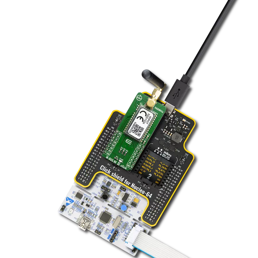
868MHz right-angle rubber antenna is a compact and versatile solution for wireless communication. Operating within the frequency range of 868-915MHz, it ensures optimal signal reception and transmission. With a 50-ohm impedance, it's compatible with various devices and systems. This antenna boasts a 2dB gain, enhancing signal strength and extending communication range. Its vertical polarization further contributes to signal clarity. Designed to handle up to 50W of input power, it's a robust choice for various applications. Measuring just 48mm in length, this antenna is both discreet and practical. Its SMA male connector ensures a secure and reliable connection to your equipment. Whether you're working with IoT devices, remote sensors, or other wireless technologies, the 868MHz right-angle antenna offers the performance and flexibility you need for seamless communication.

Used MCU Pins
mikroBUS™ mapper
Take a closer look
Click board™ Schematic

Step by step
Project assembly

Start by selecting your development board and Click board™. Begin with the EasyPIC v7a as your development board.


Track your results in real time
Application Output
1. Application Output - In Debug mode, the 'Application Output' window enables real-time data monitoring, offering direct insight into execution results. Ensure proper data display by configuring the environment correctly using the provided tutorial.

2. UART Terminal - Use the UART Terminal to monitor data transmission via a USB to UART converter, allowing direct communication between the Click board™ and your development system. Configure the baud rate and other serial settings according to your project's requirements to ensure proper functionality. For step-by-step setup instructions, refer to the provided tutorial.

3. Plot Output - The Plot feature offers a powerful way to visualize real-time sensor data, enabling trend analysis, debugging, and comparison of multiple data points. To set it up correctly, follow the provided tutorial, which includes a step-by-step example of using the Plot feature to display Click board™ readings. To use the Plot feature in your code, use the function: plot(*insert_graph_name*, variable_name);. This is a general format, and it is up to the user to replace 'insert_graph_name' with the actual graph name and 'variable_name' with the parameter to be displayed.

Software Support
Library Description
This library contains API for ISM RX 3 Click driver.
Key functions:
ismrx3_reset- Reset function.ismrx3_get_data- Read data output.ismrx3_get_clk- Read clock output.
Open Source
Code example
The complete application code and a ready-to-use project are available through the NECTO Studio Package Manager for direct installation in the NECTO Studio. The application code can also be found on the MIKROE GitHub account.
/*!
 * @file main.c
 * @brief ISMRX3 Click example
 *
 * # Description
 * This example showcases ability of Click board to configure
 * and read incoming rf signal and parses data using data and clock line.
 *
 * The demo application is composed of two sections :
 *
 * ## Application Init
 * Initialization of communication modules (SPI, UART), and additional
 * communication pins. Resets device, reads device ID, and sets default
 * configuration that sets ASK modulation and 433.92MHz with 5bps data rate.
 *
 * ## Application Task
 * Reads clock pin and gets samples of data pin state, converts it in manchester
 * data that is stored in a buffer. When it fills out manchester buffer checks if
 * expected preamble data is received. If it is, checks the next byte(it should be
 * received data length). Then parses rest of data and if it's correct shows it on log.
 *
 * @note
 * The expected data that is received is:
 * _PREAMBLE_WORD_(2bytes), _DATA_LENGTH_(1byte), _DATA_(1..255bytes)
 *
 * By default _PREAMBLE_WORD_ is set to be 0xAAAA.
 *
 * @author Luka FIlipovic
 *
 */

#include "board.h"
#include "log.h"
#include "ismrx3.h"
#include "string.h"

static ismrx3_t ismrx3;
static log_t logger;

#define MANCHESTER_BUF_LEN  1500/*<Manchester buffer size*/
#define PREAMBLE_WORD       "01100110011001100110011001100110"/*<Preamble word,
                                                                by default: 0xAAAA*/

uint8_t manchester_buf[ MANCHESTER_BUF_LEN ] = { 0 };/*<Manchester buffer*/

static uint16_t manchester_counter;/*<Manchester data counter*/
static uint8_t last_sample;/*<Last data pin state from clock sample*/
static uint8_t sample;/*<Data pin state from clock sample*/
static uint8_t consecutive;/*<Consecutive number of same data pin state from clock sample*/

/**
 * @brief Parse and convert manchester buffer.
 * @details This function checks if preamble data is received.
 * If received converts manchester data buffer to data and logs result.
 * @param[in] ctx : Click context object.
 * See #ismrx3_t object definition for detailed explanation.
 * @return @li @c  0 - Success,
 *         @li @c -1 - Didn't find preamble,
 *         @li @c -1 - Data not complete.
 *
 * See #err_t definition for detailed explanation.
 * @note Expected data to receive:
 * PREAMBLE_WORD(0xAAAA), DATA_LEN(0x6), DATA("MikroE").
 */
static err_t parse_samples( void );

void application_init ( void )
{
    log_cfg_t log_cfg;  /**< Logger config object. */
    ismrx3_cfg_t ismrx3_cfg;  /**< Click config object. */

    /**
     * Logger initialization.
     * Default baud rate: 115200
     * Default log level: LOG_LEVEL_DEBUG
     * @note If USB_UART_RX and USB_UART_TX
     * are defined as HAL_PIN_NC, you will
     * need to define them manually for log to work.
     * See @b LOG_MAP_USB_UART macro definition for detailed explanation.
     */
    LOG_MAP_USB_UART( log_cfg );
    log_init( &logger, &log_cfg );
    log_info( &logger, " Application Init " );

    // Click initialization.
    ismrx3_cfg_setup( &ismrx3_cfg );
    ISMRX3_MAP_MIKROBUS( ismrx3_cfg, MIKROBUS_1 );
    err_t init_flag  = ismrx3_init( &ismrx3, &ismrx3_cfg );
    if ( init_flag == SPI_MASTER_ERROR )
    {
        log_error( &logger, " Application Init Error. " );
        log_info( &logger, " Please, run program again... " );

        for ( ; ; );
    }

    ismrx3_reset( &ismrx3 );

    uint8_t read_data;
    ismrx3_generic_read( &ismrx3, 0x1E, &read_data );
    log_info( &logger, " > ID: 0x%.2X", ( uint16_t )read_data );
    Delay_ms ( 500 );

    ismrx3.modulation = ISMRX3_MODULATION_ASK;
    ismrx3.reference_freq = ISMRX3_FREQUENCY_MHZ_433p92;
    ismrx3.data_rate = ISMRX3_DATA_RATE_KBPS_5;
    ismrx3.freq_deviation = ISMRX3_DEVIATION_KHZ_40;

    if ( ISMRX3_ERROR == ismrx3_default_cfg ( &ismrx3 ) )
    {
        log_error( &logger, " Configuration Error. " );
        log_info( &logger, " Please, change device configuration parameters and run program again... " );

        for ( ; ; );
    }

    manchester_counter = 0;
    log_info( &logger, " Application Task " );
}

void application_task ( void )
{
    if ( ismrx3_get_clk( &ismrx3 ) )
    {
        sample = ismrx3_get_data( &ismrx3 );
        if ( last_sample == sample )
        {
            consecutive++;
        }
        else
        {
            if ( consecutive < 4 )//Single sample
            {
                manchester_buf[ manchester_counter++ ] = last_sample + 48;//Convert to ascii 1/0
            }
            else if ( consecutive < 6 )//Two samples
            {
                manchester_buf[ manchester_counter++ ] = last_sample + 48;//Convert to ascii 1/0
                manchester_buf[ manchester_counter++ ] = last_sample + 48;//Convert to ascii 1/0
            }
            consecutive = 1;
            last_sample = sample;
        }

        while ( ismrx3_get_clk( &ismrx3 ) );
    }

    if ( manchester_counter >= MANCHESTER_BUF_LEN - 1 )
    {
        parse_samples(  );
        manchester_counter = 0;
    }
}

int main ( void )
{
    /* Do not remove this line or clock might not be set correctly. */
    #ifdef PREINIT_SUPPORTED
    preinit();
    #endif

    application_init( );

    for ( ; ; )
    {
        application_task( );
    }

    return 0;
}

static err_t parse_samples( void )
{
    //check preamble data
    char * __generic_ptr manchester_data = strstr( manchester_buf, ( char * )PREAMBLE_WORD );
    if ( manchester_data )
    {
        manchester_data += strlen( ( char * )PREAMBLE_WORD );

        if ( ( strlen( manchester_data ) + 16 ) > strlen( manchester_buf ) )
        {
            return ISMRX3_ERROR_BUF_LEN;
        }

        //get data len
        uint8_t data_len = 0;
        uint8_t offset;
        for ( offset = 1; offset < 16; offset += 2 )
        {
            data_len <<= 1;
            data_len |= ( *( manchester_data + offset )- 48 );
        }

        manchester_data += offset - 1;
        if ( ( strlen( manchester_data ) + ( 16 * data_len ) ) > strlen( manchester_buf ) )
        {
            return ISMRX3_ERROR_BUF_LEN;//Not whole data captured in sample
        }

        log_printf( &logger, "> Length: %d\r\n", ( uint16_t )data_len );

        //get data
        log_printf( &logger, "> Data: " );
        for ( uint8_t data_bytes = 0; data_bytes < data_len; data_bytes++ )
        {
            uint8_t data_byte;
            for ( offset = 1; offset < 16; offset += 2 )
            {
                data_byte <<= 1;
                data_byte |= ( *( manchester_data + offset )- 48 );
            }
            log_printf( &logger, "%c", data_byte );
            manchester_data += offset - 1;
        }
        log_printf( &logger, "\r\n" );
        return ISMRX3_OK;
    }
    return ISMRX3_ERROR;
}

// ------------------------------------------------------------------------ END