Ensure a stable, long-range connection that meets your specific needs with CC1120 and PIC18F46K80
Sub-Gigahertz innovation for your next project!

Published Nov 01, 2023
Click board™
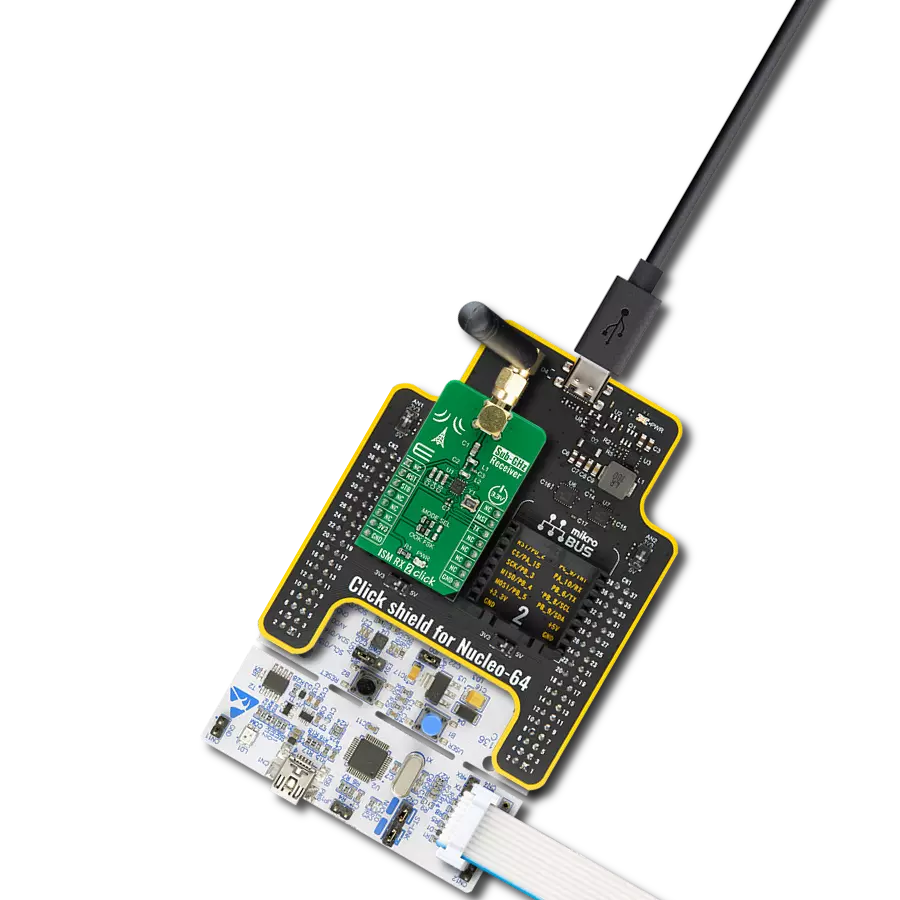
ccRF3 Click
Dev. board
EasyPIC v7
Compiler
NECTO Studio
MCU
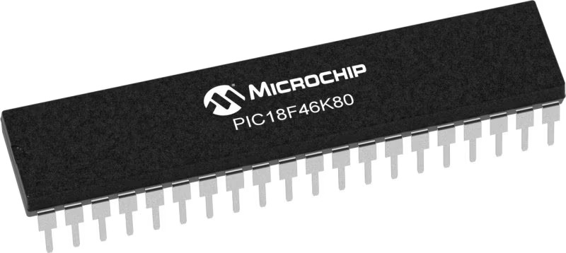
PIC18F46K80
Our solution seamlessly integrates sub-gigahertz wireless communication, enhancing your project's connectivity and ensuring data flows smoothly across all devices.
A
A
Hardware Overview
How does it work?
ccRF3 Click is based on the CC1120, a high-performance RF transceiver for narrowband systems from Texas Instruments. At the center of the CC1120, there is a fully integrated fractional-N ultra-high-performance frequency synthesizer, which brings excellent phase noise performance, providing very high selectivity and blocking performance. This flexible receiver is amplified by a low noise amplifier (LNA) and converted in quadrature (I/Q) to the intermediate frequency (IF), after which high dynamic range ADCs digitize the signals. The transmitter is based on direct synthesis of the RF frequency, so to use the spectrum effectively, the CC1120 has extensive data filtering and shaping in TX mode to support high throughput data communication in narrowband channels. The CC1120 also brings down other techniques like eWOR, sniff mode, antenna diversity, WaveMatch, and more. Antenna diversity can increase performance if enabled in a multipath environment, while the CC1120
automatically controls the required onboard antenna switch. The AGC module of the CC1120 returns an estimate of the signal strength (RSSI) received by the antenna. In addition, there is also an integrated temperature sensor for FS calibration. The transmission is done by one of the supported modulations (2-FSK, 2-GFSK, 4-FSK, MSK, and OOK). Besides the support for retransmissions and automatic acknowledgment of received packages, the CC1120 also has TCXO, power modes, built-in coding gain support for increased range and robustness, and many more. The CC1120 uses an SPI serial interface to communicate with the host MCU. In addition, this Click board™ features an RST pin for resetting the CC1120 and a few user-configurable pins labeled GP0, GP2, and GP3 that can be used for monitoring different signals or setting modes. The Clear Channel Assessment (CCA) indicates if the current channel is free or busy with two flags available on GP2 and GP0 while the current CCA
state is viewable on GP3. In synchronous serial operation mode, GP0 is explicitly used for serial data input for TX operation. The ccRF 2 Click uses u.Fl connector for adding the appropriate u.Fl Sub-GHz antenna, offered by Mikroe, and it shouldn’t be powered up without one according to the used frequency. Also, this Click board™ features a 433MHz impedance-matched, multi-function, integrated ceramic passive component switch for the Texas Instruments CC1120 chipset. The CC1120 can be configured using the SmartRF™ Studio software. SmartRF™ Studio is highly recommended for obtaining optimum register settings and evaluating performance and functionality. This Click board™ can be operated only with a 3.3V logic voltage level. The board must perform appropriate logic voltage level conversion before using MCUs with different logic levels. Also, it comes equipped with a library containing functions and an example code that can be used as a reference for further development.


Features overview
Development board
EasyPIC v7 is the seventh generation of PIC development boards specially designed to develop embedded applications rapidly. It supports a wide range of 8-bit PIC microcontrollers from Microchip and has a broad set of unique functions, such as a powerful onboard mikroProg programmer and In-Circuit debugger over USB-B. The development board is well organized and designed so that the end-user has all the necessary elements in one place, such as switches, buttons, indicators, connectors, and others. With four different connectors for each port, EasyPIC v7 allows you to connect accessory boards, sensors, and custom electronics more efficiently than ever. Each part of
the EasyPIC v7 development board contains the components necessary for the most efficient operation of the same board. An integrated mikroProg, a fast USB 2.0 programmer with mikroICD hardware In-Circuit Debugger, offers many valuable programming/debugging options and seamless integration with the Mikroe software environment. Besides it also includes a clean and regulated power supply block for the development board. It can use various external power sources, including an external 12V power supply, 7-23V AC or 9-32V DC via DC connector/screw terminals, and a power source via the USB Type-B (USB-B) connector. Communication options such as
USB-UART and RS-232 are also included, alongside the well-established mikroBUS™ standard, three display options (7-segment, graphical, and character-based LCD), and several different DIP sockets. These sockets cover a wide range of 8-bit PIC MCUs, from PIC10F, PIC12F, PIC16F, PIC16Enh, PIC18F, PIC18FJ, and PIC18FK families. EasyPIC v7 is an integral part of the Mikroe ecosystem for rapid development. Natively supported by Mikroe software tools, it covers many aspects of prototyping and development thanks to a considerable number of different Click boards™ (over a thousand boards), the number of which is growing every day.

Microcontroller Overview
MCU Card / MCU
Architecture
PIC
MCU Memory (KB)
64
Silicon Vendor
Microchip
Pin count
40
RAM (Bytes)
3648
You complete me!
Accessories
IPEX-SMA cable is a type of RF (radio frequency) cable assembly. "IPEX" refers to the IPEX connector, a miniature coaxial connector commonly used in small electronic devices. "SMA" stands for SubMiniature Version A and is another coaxial connector commonly used in RF applications. An IPEX-SMA cable assembly has an IPEX connector on one end and an SMA connector on the other, allowing it to connect devices or components that use these specific connectors. These cables are often used in applications like WiFi or cellular antennas, GPS modules, and other RF communication systems where a reliable and low-loss connection is required.

Right angle 433MHz rubber antenna boasts a frequency range of 433MHz, ensuring optimal performance within this spectrum. With a 50Ohm impedance, it facilitates efficient signal transmission. The antenna's vertical polarization enhances signal reception in a specific orientation. Featuring a 1.5dB gain, it can improve signal strength to some extent. The antenna can handle a maximum input power of 50W, making it suitable for various applications. Its compact 50mm length minimizes spatial requirements. Equipped with an SMA male connector, it easily interfaces with compatible devices. This antenna is an adaptable solution for wireless communication needs, particularly when vertical polarization is crucial.

Used MCU Pins
mikroBUS™ mapper
Take a closer look
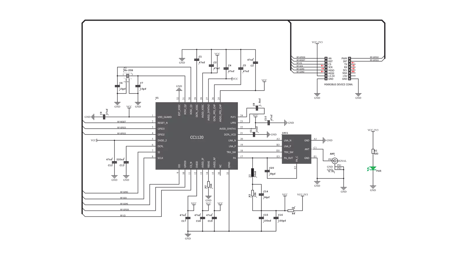
Click board™ Schematic
Step by step
Project assembly

Start by selecting your development board and Click board™. Begin with the EasyPIC v7 as your development board.


Track your results in real time
Application Output
1. Application Output - In Debug mode, the 'Application Output' window enables real-time data monitoring, offering direct insight into execution results. Ensure proper data display by configuring the environment correctly using the provided tutorial.

2. UART Terminal - Use the UART Terminal to monitor data transmission via a USB to UART converter, allowing direct communication between the Click board™ and your development system. Configure the baud rate and other serial settings according to your project's requirements to ensure proper functionality. For step-by-step setup instructions, refer to the provided tutorial.

3. Plot Output - The Plot feature offers a powerful way to visualize real-time sensor data, enabling trend analysis, debugging, and comparison of multiple data points. To set it up correctly, follow the provided tutorial, which includes a step-by-step example of using the Plot feature to display Click board™ readings. To use the Plot feature in your code, use the function: plot(*insert_graph_name*, variable_name);. This is a general format, and it is up to the user to replace 'insert_graph_name' with the actual graph name and 'variable_name' with the parameter to be displayed.

Software Support
Library Description
This library contains API for ccRF3 Click driver.
Key functions:
ccrf3_cmd_strobe- Set command strobe function.ccrf3_send_tx_data- Send TX data function.ccrf3_receive_rx_data- Receive RX data function.
Open Source
Code example
The complete application code and a ready-to-use project are available through the NECTO Studio Package Manager for direct installation in the NECTO Studio. The application code can also be found on the MIKROE GitHub account.
/*!
 * @file main.c
 * @brief ccRF3 Click example
 *
 * # Description
 * This example demonstrates the use of ccRF 3 Click board.
 *
 * The demo application is composed of two sections :
 *
 * ## Application Init
 * Initializes the driver, performs the default configuration and enables the selected mode.
 *
 * ## Application Task
 * Depending on the selected mode, it reads the received data or sends the desired message
 * every 2 seconds. All data is being logged on the USB UART where you can track their changes.
 *
 * @author Stefan Ilic
 *
 */

#include "board.h"
#include "log.h"
#include "ccrf3.h"

#define TEXT_TO_SEND "MikroE\r\n"

static ccrf3_t ccrf3;
static log_t logger;
static uint8_t rx_buffer[ 255 ];

#define DEMO_APP_TRANSMITTER

void application_init ( void )
{
    log_cfg_t log_cfg;  /**< Logger config object. */
    ccrf3_cfg_t ccrf3_cfg;  /**< Click config object. */

    /**
     * Logger initialization.
     * Default baud rate: 115200
     * Default log level: LOG_LEVEL_DEBUG
     * @note If USB_UART_RX and USB_UART_TX
     * are defined as HAL_PIN_NC, you will
     * need to define them manually for log to work.
     * See @b LOG_MAP_USB_UART macro definition for detailed explanation.
     */
    LOG_MAP_USB_UART( log_cfg );
    log_init( &logger, &log_cfg );
    log_printf( &logger, " Application Init \r\n" );

    // Click initialization.
    ccrf3_cfg_setup( &ccrf3_cfg );
    CCRF3_MAP_MIKROBUS( ccrf3_cfg, MIKROBUS_1 );
    if ( SPI_MASTER_ERROR == ccrf3_init( &ccrf3, &ccrf3_cfg ) )
    {
        log_error( &logger, " Communication init." );
        for ( ; ; );
    }

    log_printf( &logger, "----------------------\r\n" );
    log_printf( &logger, " Hardware reset\r\n" );
    ccrf3_hw_reset( &ccrf3 );
    Delay_ms ( 1000 );

    if ( CCRF3_ERROR == ccrf3_default_cfg ( &ccrf3 ) )
    {
        log_error( &logger, " Default configuration." );
        for ( ; ; );
    }

    log_printf( &logger, "----------------------\r\n" );
#ifdef DEMO_APP_TRANSMITTER
    ccrf3_set_tx_mode( &ccrf3 );

    log_printf( &logger, " Transmitter mode\r\n" );
#else
    ccrf3_set_rx_mode( &ccrf3 );

    log_printf( &logger, " Receiver mode\r\n" );
#endif

    log_printf( &logger, "----------------------\r\n" );
    Delay_ms ( 100 );

    log_printf( &logger, " Application Task \r\n" );
    log_printf( &logger, "----------------------\r\n" );
}

void application_task ( void )
{
#ifdef DEMO_APP_TRANSMITTER
    ccrf3_send_tx_data( &ccrf3, TEXT_TO_SEND, strlen( TEXT_TO_SEND ) );
    log_printf( &logger, " Sent message: MikroE\r\n" );
    log_printf( &logger, " Packet number: %u\r\n", ccrf3.packet_counter );
    log_printf( &logger, "----------------------\r\n" );
    Delay_ms ( 1000 );
    Delay_ms ( 1000 );
#else
    uint8_t num_bytes = ccrf3_receive_rx_data( &ccrf3, &rx_buffer[ 0 ] );
    if ( num_bytes )
    {
        log_printf( &logger, " Received message: " );
        for ( uint8_t cnt = 3; cnt < rx_buffer[ 0 ]; cnt++ )
        {
            log_printf( &logger, "%c", rx_buffer[ cnt ] );
        }
        log_printf( &logger, " Packet number: %u", ccrf3.packet_counter );
        log_printf( &logger, "\r\n----------------------\r\n" );
    }
#endif
}

int main ( void )
{
    /* Do not remove this line or clock might not be set correctly. */
    #ifdef PREINIT_SUPPORTED
    preinit();
    #endif

    application_init( );

    for ( ; ; )
    {
        application_task( );
    }

    return 0;
}

// ------------------------------------------------------------------------ END
Additional Support
Resources
Category:Sub-1 GHz Transceievers